Understanding and Specifying Anodizing:
what a Manufacturer Needs to Know…
© 2014, Joseph H Osborn.
Author: Joseph H Osborn, OMW Corporation, email: joeo@omwcorp.com
Why Anodizing?
Anodizing is perhaps the most commonly specified finish for aluminum machined parts. Advantages of
Anodizing include:
1.) A very thin coating (.0002-.0012” for Type II) compared to paints and powder coat. Coating
thickness can often be ignored for machined parts.
2.) Extremely durable, hard, abrasion resistant and long lasting. Coating does not peel or chip.
Much, much harder surface than paint (harder than tool steel). Coating lasts indefinitely.
3.) Some types (e.g., architectural anodizing) have colors which are fade resistant in sunlight
nearly indefinitely.
4.) Excellent corrosion protection. Withstands salt-spray and other tests extremely well.
5.) Environmentally friendly finish. Can be readily recycled. Production involves simple
inorganic chemicals which have minimal environmental impact.
6.) Good electrical insulator. Combined with other coatings can be used for selective masking of
low-voltage currents.
7.) Inexpensive. Very price competitive with painting and powder coating.
Conversion Coating: what it means
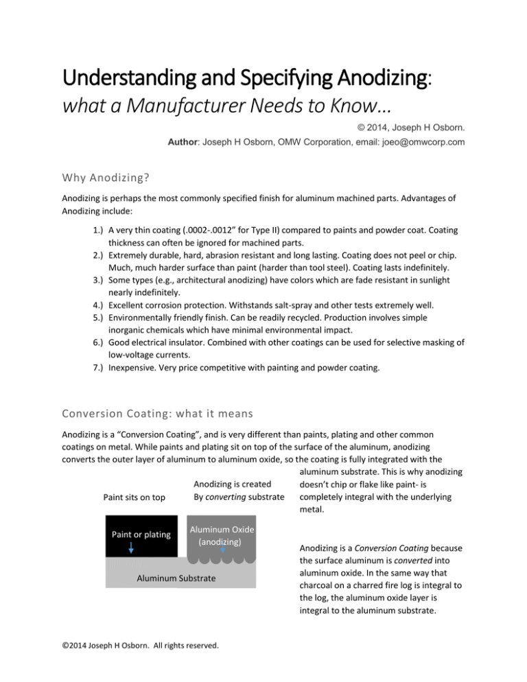
Anodizing is a “Conversion Coating”, and is very different than paints, plating and other common
coatings on metal. While paints and plating sit on top of the surface of the aluminum, anodizing
converts the outer layer of aluminum to aluminum oxide, so the coating is fully integrated with the
aluminum substrate. This is why anodizing
Anodizing is created
doesn’t chip or flake like paint- is
By converting substrate
completely integral with the underlying
Paint sits on top
metal.
Paint or plating
Aluminum Oxide
(anodizing)
Aluminum Substrate
©2014 Joseph H Osborn. All rights reserved.
Anodizing is a Conversion Coating because
the surface aluminum is converted into
aluminum oxide. In the same way that
charcoal on a charred fire log is integral to
the log, the aluminum oxide layer is
integral to the aluminum substrate.
The oxide coating is most commonly created by placing an aluminum part in a sulfuric acid bath while
running a low-voltage DC current through the part to cathodes on the side of the tank. The part acts as
the anode in the electrical circuit, hence the origin of the term “Anod-izing”
Types of Anodizing
Most anodizing on machined parts are of two commonly specified types: Type II (or “regular”) sulfuric
anodizing and Type III Hardcoat or “hard” sulfuric anodizing. The Type II & III designators come from the
common Military specification, MIL-A-8625 (there is also a Type I anodizing, but this is done using
environmentally-unfriendly chromic acid, and it is rarely specified these days).
Both Type II and Type III “hard” anodizing are very hard coatings. Type III “hard” anodizing is done at a
lower temperature, is more expensive, and a little harder than Type II, but you need special equipment
to tell the difference in practical terms. Type III, however, is much thicker than Type II, typically .002” vs.
.0006” respectively, which makes it more resistant to scratching and heavy wear.
There is another type of anodizing, commonly called “architectural” anodizing. It is essentially the same
as Type II anodizing above, but uses metallic ion dying which is completely colorfast in sunlight.
Anodize vs Alodine (Chem Film)
Alodine is a trade name for chemical conversion coating of aluminum (also called “chem film” or
“chemical conversion coating”). Because the name sounds a bit like anodize, there is sometimes
confusion between the two coatings. While both are conversion coatings, chem film is much thinner
than anodizing and is also created by immersion but without use of electrical current. Unlike anodizing,
chem films (which are commonly seen in gold or ROHS clear versions) provide a conductive coating, and
are sometimes used in conjunction with masking in anodized parts. The coating provides corrosion
protection and also is an excellent base primer for paints. The common military specification for
chemical conversion coating is MIL-DTL-5541.
Understanding coating thickness and build-up
Because anodizing is a conversion coating, the surface of the aluminum actually recedes dimensionally
as the aluminum is converted to the anodized oxide layer. The oxide layer grows out from the aluminum
©2014 Joseph H Osborn. All rights reserved.
at a greater rate than the aluminum is removed, so the anodizing layer will tend to add thickness to
dimensioned surfaces.
When specifying anodizing from a mechanical designer’s perspective, it is extremely important to
understand the terms used by the anodizer, since these cause much confusion. Coating Thickness is the
actual thickness of the oxide layer. This is not the same as Build-up, which is a common term for the
dimensional difference between the oxide layer and the originally aluminum surface (see figure above).
Eddy current thickness testing meters are usually used to measure the anodized (oxide) layer. This will
measure coating thickness, but not build-up. Build-up must be measured by comparing a finished part to
an uncoated sample, or by calculation.
Calculating Build-up
Anodizers usually use a rule of thumb that the oxide layer penetrates 50% into the part and builds up
50%. The true percentages, according to most sources, are closer to 67% in and 33% out for the
common Type II anodizing, and 50% in and 50% out for Type III, hardcoat anodizing. In any case,
knowing the coating thickness and using these percentages, a rough calculation of build-up is possible.
Heavy etching before anodizing can also reduce buildup, by removing up to a few tenths of aluminum
before the anodic layer is formed.
Machining Tolerancing
With common Type II anodizing, the coating thickness will usually vary from .0002” to .0012”. The
thinnest coatings are usually seen in clear anodizing, since anodizing dyes require at least .0004”- .0006”
of coating thickness to dye properly. With an average coating thickness of .0008”, the build-up will
typically be .0002”-.0003”, which is small enough that it can be effectively ignored in most machined
and fabricated parts. This is not the case, however, with Type III, Hardcoat anodizing, which can have
coating thicknesses of up to .004”, and build-up to .002”.
Threads, holes and masking
Even with thinner, Type II anodizing, coating build-up can cause problems with tolerancing, for example,
with very fine threaded holes, precision pin holes, and fine sliding fits.
The most common solution to this problem is to mask the features. This is done using soft plastic plugs,
for round holes, or plastic tape or painted-on liquid plastics for flat areas.
As noted above, masking is often not required for Type II anodizing. However, it should be noted on
print call outs when specifying thicker Type III coatings and when small thread or tight tolerance
features exist.
©2014 Joseph H Osborn. All rights reserved.
Silicon rubber plugs, such as these, are often used to
mask high tolerance holes prior to anodizing.
Variation in Coating Thickness
While general coating thickness can be specified on a print, most anodizers will be leery of certifying an
exact uniform coating thickness. This is because coating thickness will vary on a part due to part
geometry, racking position, and the electrical field variations that inevitably exist in every anodizing
tank. A variation of .0001-.0003 in coating thickness on a single part is common. While uniformity of
thickness can be controlled to some degree by cathode placement, racking, and positioning in the tank,
it is still as much an art as a science, and tight thickness tolerancing can be extremely expensive if even
achievable.
Cost factors in Anodizing
Designers are often surprised by the cost to anodize what may appear at first glance to be a relatively
simple part. They are a number of factors that affect part cost:
Hard vs. regular anodizing: Since hard Type III anodizing is performed at a much lower
temperature than regular Type II anodizing, and at higher current and voltage, it
requires much higher energy use, and is usually considerably more expensive.
Masking: Masking usually involves a significant amount of hand work, which adds to
cost. Masking materials often cannot be reused and add to costs as well.
Racking: Difficult-to-rack parts can add to cost. If needed, discuss adding racking
features with your anodizer when needed on high-volume, low-cost parts.
Small features which trap chemistry: Small holes, especially blind holes, as well as
small, deep pockets or other enclosed features force extensive rinsing of parts and raise
labor costs.
Poor Specification: Poorly written or missing specifications on drawings mean more
time spent on clarification and more cost. The more clearly the anodizing is defined on a
drawing, with clear notes on racking, masking and other desired specifications, the
better.
©2014 Joseph H Osborn. All rights reserved.
“Clear” Anodizing
“Clear” anodizing is really a misnomer, as undyed anodizing is not really clear. “Clear” anodizing varies
from a very light gray for very thin coatings (.0001-.0003”) to a dark olive color for thick Type III coatings
(.002 or greater). Very thin clear anodizing (sometimes called “cosmetic” clear) coatings mimic the look
of bare aluminum (though the coating is actually slightly gray), hence the term “clear” anodizing. But on
thick hardcoated parts, the coloring is anything but clear.
Both these parts are examples of undyed,
“clear” anodizing, the only difference is the
thickness of the anodizing!
The coating of these parts ranges from .0003” on the left to greater than .002” on the right- all are
undyed.
©2014 Joseph H Osborn. All rights reserved.
Common Dyed Anodizing
An anodizing layer may be dyed or undyed. In the 8625 Mil spec, the term “Class” is used to designate
this: Class 1 is clear or undyed, and Class 2 is dyed.
Anodizing layers are commonly dyed with organic dyes by dipping the part into a hot dye tank directly
after anodizing. A wide variety of colors can be obtained through this process. By far the most
commonly specified color is black, followed by blues, reds and golds. Note that only Type II anodizing
can be dyed a variety of colors. Type III “hard” anodizing, which is quite dark even when undyed, is
typically left clear or dyed black.
Photo: An example of anodized parts dyed red
Colors and Color Matching
It is important to note that colors obtained through dying
are not as consistent as those obtained through painting
or powder coat. There is no such thing as a pantone
matched color in most commercial anodizing, and
consistency in color and color matching is extremely
difficult. Generally colors are specified in a broader way
than with painting, e.g., you would specify “blue” or
perhaps “light blue” or “dark blue” for an anodized part,
not “deep sky blue” or “electric indigo blue”.
Note that colors obtained through organic dyes are not
absolutely colorfast, especially in high UV exposure
situations. All organically dyed parts will fade to some
degree over time. Outdoors, the fading can be dramatic.
Dying in Fade–resistant Architectural Anodizing
There is a second, less common dying process known as 2-step electrolytic dying. In this process, the
anodizing layer is the same as regular Type II anodizing, but at the dying stage, instead of organic dyes,
inorganic metallic dyes are used in combination with an electric current. While the range of colors is far
more limited than with organic dyes (generally light through very dark, nearly black bronzes), the colors
are extremely resistant to fading, and will last indefinitely even in very high UV environments.
©2014 Joseph H Osborn. All rights reserved.
Photo: Two black parts, after being
placed in intense direct sunlight for
approximately 8 months. Both parts
started with a similar black color. The
bottom part used common organic
black dye and has noticeably faded.
The top part was dyed using a 2-step
electrolytic process (“architectural
anodizing”) and shows no fading.
Defects in Metal and their Effects on Anodizing
Because anodizing is a conversion coating, and relies on the aluminum substrate being converted to
aluminum oxide, any defects in the aluminum will have marked effects on the quality of the anodizing.
The basic rule to remember is that the aluminum finish must be consistent, clean and fully exposed for
the anodic layer to form properly.
Common problems occur with welds, extrusions, cold or hot-worked areas, or poorly machined surfaces.
It is common for problems in the material or mechanical finish to have the appearance of a problem
with the anodizing. Often material defects will look like chemical spotting or streaking, when the issue is
material based. GIGO (garbage in, garbage out) is truer with anodizing than nearly any other finish. For
the anodic layer to be perfect, the aluminum substrate has to be perfect as well.
This blemish looks very much like a chemical
spot, but it isn’t. It’s a location where a
locating pin inadvertently pushed up the
sheet metal. The sheet was peened back into
place by the machinist, but the cold work
altered the material enough to change the
color of the anodizing.
©2014 Joseph H Osborn. All rights reserved.
This dark spotting looks like something amiss
in the anodizing tank, but it was actually
caused by overly dirty water in a vibratory
tumbler. The dirty media was imbedded into
the aluminum finish, causing blotchy areas.
Uncharacteristically, the welds on this bike
frame caused little change in the anodizing
color. However, poor sanding and left over
spots of bondo create a surface finish that
shows unanodized blotches and mechanical
scratches.
Aluminum Alloys and their Effects on Anodizing Color
Aluminum alloys can also have an effect on anodizing. Remember, that alloying elements such as copper
and Zinc do not anodize, so high-copper or zinc alloys such as 7075 or 2024 will give noticeably different
colors than lower copper alloys such as 6061, both with dyed parts and with clear anodizing. Generally,
6061, the 3000 and 5000 series alloys will anodize reasonably consistently with each other. 7075 will
show a yellow tint in clear anodizing, due to the high Zinc content, and black will not be as deep. 1000
series, while rarely specified, actually anodizes the best of all, being the closest to pure aluminum.
©2014 Joseph H Osborn. All rights reserved.
The smaller part on the left is machined from 7075, while
the larger circular part is 6061. Note the distinctive
yellowish tint of the left hand part, which is characteristic
of clear anodizing of 7075 alloy.
The Anodic Layer
Ever wondered why anodizing dyes so well? It has to do with the microscopic structure of the anodizing
layer.
The oxide or “anodic” layer formed in the anodizing process consists of microscopic hexagonal oxide
columns with holes or “pores” which extend nearly the entire length of each column. It is these pores
which hold the dye.
The anodic layer is extremely hard- usually between 60-70 Rockwell C. The layer is also an excellent
insulator, with a .002” hardcoat layer having a breakdown voltage of 1500-2000 volts.
The characteristic hexagonal structure of anodizing
(hypothetically about 40,000x magnification). Note the
hexagonal oxide columns have been sliced through to
show the structure. An actual layer would be much
thicker, with the height of the columns 200 or more
times higher than their diameter.
©2014 Joseph H Osborn. All rights reserved.
Gap
Void
The anodic layer grows outward from the
aluminum surface as a part is anodized. As such,
very sharp inside or outside corners on a part
can cause gaps or voids to develop- especially
with thick anodic layers such as Type III hardcoat
anodizing. Avoid very sharp inside or outside
corners when possible, and allow a radius of at
least .015”(1/64th”).
Mil Spec MIL-A-8625
US Military Specification MIL-A-8625 is the most common specification for anodizing in use. Although
the specification is somewhat out of date, especially in regards to the environmental impact of some of
the processes (e.g., Type I chromic acid anodizing), it still is used as a model for much of the anodizing
specified for military and aerospace products, and forms the basis for many proprietary
company specifications.
The most common types and classes of anodizing found in MIL-A-8625 are:
Type II Sulfuric Acid Anodizing (common or “standard” anodizing)
Type III Sulfuric Acid Anodizing (hard or “hardcoat” anodizing)
Class 1 – Undyed (clear)
Class 2- Dyed (colored)
Note that MIL-A-8625 does not cover architectural anodizing, which is usually covered by a designation
system provided by the Aluminum Association (e.g., AA-M12-C22-A34, for electrolytically dyed
architectural anodizing).
As an example, a standard black part designated by MIL-A-8625 would be called out on a
drawing as follows:
“MIL-A-8625, Type II, Class 2, black”
Understanding Racking and Rack Marks
Because anodizing involves running an electric current through the part to be anodized, parts must be
gripped by conductive racks or wires. Where these racks or wires contact the part, there will be slight
unanodized marks or “contact points” left on the surface of edges of the parts. MIL-A-8625 mentions
and specifically allows for these rack marks.
©2014 Joseph H Osborn. All rights reserved.
Rack marks can be controlled by specifying on a drawing allowable locations for gripping a part. If rack
marks are critical, discuss possible racking options in advance with your anodizer.
This photo shows several different
racking approaches for parts of
different sizes and shapes. Parts
can be wired through holes,
gripped on the edges, or gripped
inside cavities with “spring”
grippers. Anywhere there is metal
to metal contact, there will be
small unanodized areas.
Assemblies and Anodizing
In general, multi-part assemblies must be anodized before assembly. Because parts are dipped in both a
strong alkaline (sodium hydroxide) and sulfuric acid, any studs, threaded inserts, pins, standoffs, etc.,
are in danger of corrosion and will cause problems in the anodizing tanks. Even stainless steel
components can corrode in the tanks during anodizing, and can affect current flow during electrolytic
processes. Gaps between components can also trap chemicals and cause problems by bleeding of the
corrosives after anodize. As a rule of thumb- assemble after anodizing.
Testing if Clear Anodizing Exists
Since thin, “cometic” clear anodizing often mimics the look of bare aluminum, it is sometimes difficult to
tell if a part has been anodized. Since anodizing is a strong insulator, an easy test is to use a volt-ohm
meter set to measure resistance. Touch both probes to the metal part- if there is a high resistance, the
part is most likely anodized.
©2014 Joseph H Osborn. All rights reserved.
Set a volt-ohm meter to measure resistance, and
touch the probes to the surface of a part you
suspect of being clear anodized. If there is high
resistance, the part is likely anodized.
Marking and Engraving Anodizing
Anodizing is an excellent background finish for either mechanical or
laser engraving. Using carbide tooling, e.g. a small 90o chamfer mill,
letters, numbers or other symbols can engraved directly through the
anodic layer with a CNC mill or router. The aluminum substrate
gives an excellent contrast to the characters.
Laser Engraving also produces excellent results. Rather than burn
through the anodic layer, a laser engraver will bleach the dye in the
layer, generally giving an excellent contrast to the characters. An
advantage of laser engraving on colored anodizing, is that no
additional chemicals need be added to the surface to accentuate
the marking, which is not the case with bare aluminum, stainless
steel, or most other metals.
An example of laser engraved
characters on a black anodized part.
Care and Cleaning of Anodizing
Anodizing is surprisingly durable and resilient to corrosion. However, like its aluminum base, it is
susceptible to strong alkalines, such as Lye or Sodium Hydroxide. It also can be damaged by strong acids,
such as nitric or sulfuric. Beware of strong alkaline cleaners, which often contain ammonia or lye, as well
as masonry or cement cleaners, which can contain strong acids.
Surprisingly, anodizing is quite resistant to organic solvents. While alcohol or acetone will quickly
remove ink from a permanent marker, for example, they will not damage or fade colored anodizing, and
can be excellent for cleaning purposes.
©2014 Joseph H Osborn. All rights reserved.
Ammonia
Alkaline Cleaners
Lye
Strong Acids
OK: Alcohol
Mild Soap/detergent
Acetone
MEK
Quick Designer Checklist:
1.) Specify type of anodizing, e.g., “Type II anodize” or “Type III hard anodize” to designate type of
coating. The Mil spec may be included if desired, e.g., “Mil 8625, Type II anodize”. Specify color
desired, e.g., “black”
Examples of proper print call-outs:
Type II anodize, black.
Mil-A-8625, Type III, Clear (or Class I)
Anodize, Type II, clear
Anodize, Type III, Black
Architectural Anodize, 2-step electrolytic, dark bronze.
2.) Think through whether masking will be required (especially with Type III hard anodizing). Call
out masking locations on print.
3.) Remember to call out acceptable racking locations if racking marks are a concern.
--------
For copies or permission to use this document, please contact Joe Osborn, OMW Corporation, 354 Bel Marin Keyes
Blvd, Novato, CA 94949. Ph. 415-382-1669. www.omwcorp.com Email: joeo@omwcorp.com
References: Aluminum Anodizer’s Council. www.anodizing.org. The Aluminum Association, www.aluminum.org
Credits: Most illustrations by author. Anodic Layer illustration by Joseph A. Osborn.
Copyright © 2014, Joseph H. Osborn. All rights reserved.
©2014 Joseph H Osborn. All rights reserved.

