i1 ITA COVER REMOVAL AND INSTALLATION
advertisement

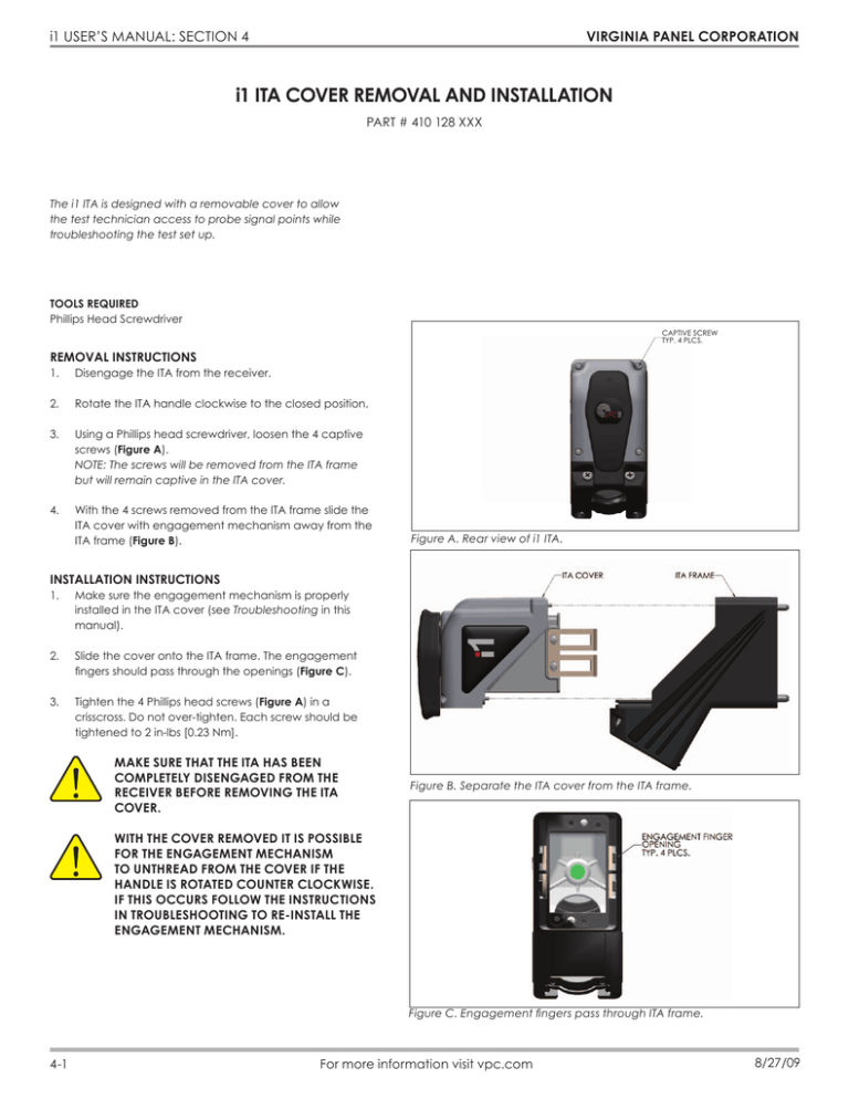
VIRGINIA PANEL CORPORATION i1 USER’S MANUAL: SECTION 4 i1 ITA COVER REMOVAL AND INSTALLATION PART # 410 128 XXX The i1 ITA is designed with a removable cover to allow the test technician access to probe signal points while troubleshooting the test set up. TOOLS REQUIRED Phillips Head Screwdriver CAPTIVE SCREW TYP. 4 PLCS. REMOVAL INSTRUCTIONS 1. Disengage the ITA from the receiver. 2. Rotate the ITA handle clockwise to the closed position. 3. Using a Phillips head screwdriver, loosen the 4 captive screws (Figure A). NOTE: The screws will be removed from the ITA frame but will remain captive in the ITA cover. 4. With the 4 screws removed from the ITA frame slide the ITA cover with engagement mechanism away from the ITA frame (Figure B). Figure A. Rear view of i1 ITA. INSTALLATION INSTRUCTIONS 1. Make sure the engagement mechanism is properly installed in the ITA cover (see Troubleshooting in this manual). 2. Slide the cover onto the ITA frame. The engagement fingers should pass through the openings (Figure C). 3. Tighten the 4 Phillips head screws (Figure A) in a crisscross. Do not over-tighten. Each screw should be tightened to 2 in-lbs [0.23 Nm]. MAKE SURE THAT THE ITA HAS BEEN COMPLETELY DISENGAGED FROM THE RECEIVER BEFORE REMOVING THE ITA COVER. Figure B. Separate the ITA cover from the ITA frame. WITH THE COVER REMOVED IT IS POSSIBLE FOR THE ENGAGEMENT MECHANISM TO UNTHREAD FROM THE COVER IF THE HANDLE IS ROTATED COUNTER CLOCKWISE. IF THIS OCCURS FOLLOW THE INSTRUCTIONS IN TROUBLESHOOTING TO RE-INSTALL THE ENGAGEMENT MECHANISM. Figure C. Engagement fingers pass through ITA frame. 4-1 For more information visit vpc.com 8/27/09 VIRGINIA PANEL CORPORATION i1 USER’S MANUAL: SECTION 5 i1 CABLE CLAMP REMOVAL AND INSTALLATION PART # 410 128 XXX TOOLS REQUIRED Phillips Head Screwdriver CABLE CLAMP REMOVAL INSTRUCTIONS STRAIN RELIEF BAR NOTE: Due to interlocking component features, the cable clamp cannot be removed unless the ITA cover is removed first (see Section 4 for cover removal instructions). 1. Remove the 6-32 x 1.50” screws and the strain relief bar (Figure A). 2. Loosen the 4-40 x 0.75” captive screws that hold the strain relief clamp to the ITA frame (Figure B). 3. Slide the filler plate away from the clamp. 6-32 x 1.50” SCREWS Figure A. Removal of the strain relief bar. 4-40 x 0.75” SCREWS, TYP 2 Figure B. Removal of the strain relief clamp. Note: The chamfered side should face toward the body of the connector. 5-1 For more information visit vpc.com 8/27/09 VIRGINIA PANEL CORPORATION i1 USER’S MANUAL: SECTION 5 i1 CABLE CLAMP REMOVAL AND INSTALLATION PART # 410 128 XXX CABLE CLAMP INSTALLATION INSTRUCTIONS 1. 2. After removing the cable clamp, mount the module into the ITA frame. See Section 6 for module mounting instructions. 6-32 x 1.50” SCREWS Next, place the wires or cables into the U-shaped section of the clamp. The filler plate of the cable clamp can be removed temporarily, if necessary (Figure A). 3. Replace the filler plate, if it was removed (Figure B). 4. 5. Mount the U-shaped clamp to the ITA frame using the 4-40 x 0.75” captive screws. Torque the screws 4-5 in-lbs [0.45 to 0.56 Nm]. Slowly alternate tightening the 6-32 x 1.50” screws until the strain relief bar has tightly closed on the cable bundle. See Figure C for completed assembly. FILLER PLATE CABLE CLAMP 4-40 x 0.75” SCREWS STRAIN RELIEF BAR Figure A. Installation of the wire bundle. NOTE: Reverse the orientation of the strain relief bar to accommodate smaller cable bundles. FORMULA TO CALCULATE THE MAXIMUM NUMBER OF WIRES IN A CABLE BUNDLE N = (1.00/d - 1)2 (.907) 1.00 = inside diameter of converted oblong bushing N = number of wires d = outside diameter of wires WIRE IS NOT LIMITED BY GAUGE. WIRE IS LIMITED BY TOTAL OVERALL OUTSIDE DIAMETER. EXAMPLE: STANDARD 22 AWG, MIL-W-22759/45 OD=0.043″ STANDARD 22 AWG, MIL-W-81044/11 OD=0.049″ SHIELDED TWISTED PAIR, 22 AWG, M27500- 22RC2S06 OD=0.136″ 5-2 Figure B. Proper orientation of filler plate. For more information visit vpc.com Figure C. Wire bundle installed with strain relief. 8/27/09 VIRGINIA PANEL CORPORATION i1 USER’S MANUAL: SECTION 6 i1 MODULE INSTALLATION AND REMOVAL RECEIVER • PART # 310 128 101 ITA • PART # 410 128 101 The i1 receiver is designed so the modules mount from the rear. This allows the test technician to easily mount wired cable assemblies without having to route the connectors through the receiver frame. TOOLS REQUIRED Phillips Head Screwdriver NOTE: The receiver strain relief plate or the ITA cover may need to be removed prior to installing or removing an i1 module. Refer to the appropriate section for instructions on how to perform these steps. NOTE: If the application requires, receiver modules can be installed in the ITA and ITA modules in the receiver. If this is done, you must be sure to switch the contacts as well (receiver contacts in a receiver module and ITA contacts in an ITA module). You should also use the keying kit to prevent attempted mating to a receiver or ITA that has a standard module orientation. WHEN USING THE I1 IN THIS CONFIGURATION, THE ALIGNMENT PINS CAN DAMAGE THE ITA CONTACTS IF THE ITA IS NOT PROPERLY ALIGNED WITH THE RECEIVER. USE CAUTION WHEN ENGAGING THE ITA TO AVOID DAMAGING PINS. Figure A. i1 receiver and receiver module. MODULE INSTALLATION 1. Place the module in the receiver or ITA until the upper and lower module screws touch the mating holes in the inner frame. Install the module such that Position 1 is located at the top of the receiver/ITA frame. 2. Using a Phillips head screwdriver, tighten the top screw 1 to 2 full revolutions while pushing lightly against the face of the module. 3. Maintain this pressure while tightening the bottom screw 1 to 2 full revolutions. 4. Repeat this sequence until the module is seated. Torque both screws 1.5 in-lbs [0.16 Nm]. MODULE REMOVAL 1. Loosen the top screw 1 to 2 full revolutions then loosen the bottom screw 1 to 2 full revolutions. 2. Repeat this sequence until the module is separated from the receiver or ITA. 6-1 Figure B. i1 ITA and ITA module. For more information visit vpc.com 5/6/11


