XSP Series
LED Street Light
Includes: XSP2L™ IP66 Luminaires
IMPORTANT SAFEGUARDS
INSTALLATION INSTRUCTIONS
When using electrical equipment, basic safety precautions should always be followed
including the following:
READ AND FOLLOW ALL SAFETY INSTRUCTIONS
1.
To reduce the risk of electrical shock, turn off power supply before installation or
servicing.
This luminaire must be installed in accordance with the NEC or your local
electrical code. If you are not familiar with these codes and requirements,
consult a qualified electrician.
If NEMA photo control is installed refer to NEMA Receptacle section for
instructions.
If mounting bolts are completely removed in the field they should be hand
threaded (prior to use of power tools) to ensure proper engagement of the
thread when re-installing. Failure to pre-start threads may result in crossthreading or stripping of the bolts during reinstallation.
2.
3.
4.
SAVE THESE INSTRUCTIONS FOR FUTURE REFERENCE
TO INSTALL:
1
2
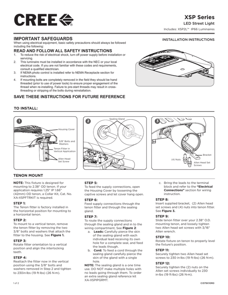
Sealing Gland
3
Housing Cover
3/8" Bolts and
Washers
Tenon Fitter in
Vertical Application
Bracket
Allen Head
Set Screw
(4) Nuts
Allen Head Set
Screws
TENON MOUNT
NOTE: This fixture is designed for
mounting to 2.38" OD tenon. If your
application requires 1.25" IP 1.66"
(42mm) OD tenon, a Collar Kit, Cat. No.
XA-XSPFTRKIT is required.
STEP 1:
The Tenon fitter is factory installed in
the horizontal position for mounting to
a horizontal tenon.
STEP 2:
To mount to a vertical tenon, remove
the tenon fitter by removing the two
3/8” bolts and washers that attach the
fitter to the housing. See Figure 1.
STEP 3:
Rotate fitter orientation to a vertical
position and align the interlocking
teeth.
STEP 4:
Reattach the fitter now in the vertical
position using the 3/8" bolts and
washers removed in Step 2 and tighten
to 230in·lbs (19 ft·lbs) (26 N·m).
1 of 2
STEP 5:
To feed the supply connections, open
the Housing Cover by loosening the
captive screws and let cover hang open.
STEP 6:
c. Bring the leads to the terminal
block and refer to the “Electrical
Connections” section for wiring
instruction.
STEP 8:
Feed supply connections through the
tenon fitter and through the sealing
gland.
Insert supplied bracket, (2) Allen head
set screws and (4) nuts into tenon fitter.
See Figure 3.
STEP 7:
STEP 9:
To route the supply connections
through the sealing gland and in to the
wiring compartment, See Figure 2:
a. Leads: Carefully pierce the skin
of the sealing gland with each
individual lead receiving its own
hole for a complete seal, and feed
the leads though.
b. Cord: To feed a cord through the
sealing gland carefully pierce the
skin of the gland with a single
hole.
NOTE: The sealing gland is a one time
use. DO NOT make multiple holes with
no leads going through them. To order
an extra sealing gland reference kit
XA-XSPIPGRMT.
Slide tenon fitter over your 2.38" O.D.
mounting tenon, and loosely tighten
two Allen head set screws with 3/16"
Allen wrench.
STEP 10:
Rotate fixture on tenon to properly level
the fixture’s position.
STEP 11:
Securely tighten two Allen head set
screws to 230 in·lbs (19 ft·lbs) (26 N·m).
STEP 12:
Securely tighten the (2) nuts on the
Allen set screws individually to 230
in·lbs (19 ft·lbs) (26 N·m).
CI379X10R0
NEMA RECEPTACLE (OPTIONAL)
4
STEP 1:
DO NOT loosen/tighten flat head screws for the NEMA receptacle.
STEP 2:
Rotational adjustment of the photo control is tool-less.
STEP 3:
Engage/install photo control into NEMA receptacle on top of the
fixture.
B C
F G
I
A
DRV 1 2 3 4 5 DRV CRTL
D E
STEP 4:
Firmly rotate photo-control with its photo-eye approximately in the ‘N’
north direction. Some photo-controls operate best somewhere between
NW and NE.
FIELD ADJUSTABLE DIMMING (OPTIONAL)
NOTE: This luminaire may be provided with field adjustable dimming.
Luminaires leave the factory adjusted to the maximum setting specified
when ordered. Visit www.cree.com/Lighting/Document-Library for
product dimming spec sheet.
STEP 1:
The Dimming module is located inside the luminaire. Open the cover by
loosening the captive D-ring and allow the cover to swing open.
STEP 2:
Establish the desired input power multiplier by referring to the product
dimming spec sheet and turn the switch to the correlating position
STEP 3:
Adjust the Dimming Module, see Figure 4, to the selected position and
close the cover ensuring no wires are pinched.
NOTE: The Utility Option will be limited to the highest setting ordered.
ELECTRICAL CONNECTIONS
PHASE TO NEUTRAL WIRING
STEP 1:
Make the following Electrical Connections to the terminal
block:
a. Connect the black fixture lead to the voltage supply position of the terminal block or Hot 1 (for 208/240V
wiring).
b. Connect the white fixture lead to the neutral supply
position of the terminal block or Hot 2 (for 208/240V
wiring).
c. Connect the green or green/yellow ground lead to
the green wire position of the terminal block.
d. If Dimming is an option; connect the violet dimming
positive lead to the supply dimming positive lead.
e. If Dimming is an option; connect the grey dimming
negative lead to the supply dimming negative lead
STEP 2:
Push excess supply wires into pole.
STEP 3:
Close cover re-tighten the captive D-ring, making sure that no
wires are pinched and latches are fully engaged.
© 2014 Cree, Inc. All rights reserved. For informational purposes only. Content is subject to change. See
www.cree.com/lighting/products/warranty for warranty and specifications. Cree® and the Cree logo are
registered trademarks, and XSP2L™ is a trademark of Cree, Inc.
2 of 2
www.cree.com/lighting
CI379X10R0


