Electronic Pressure Switches
advertisement
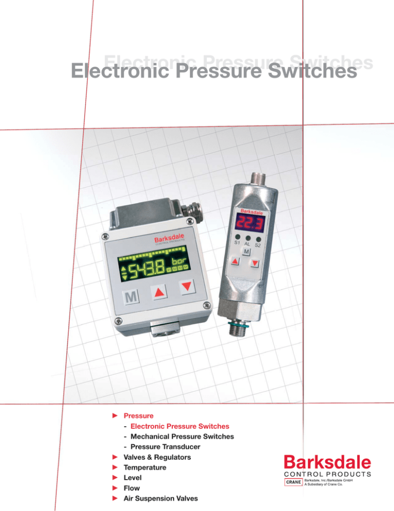
Electronic Pressure Switches Electronic Pressure Switches c Pressure - Electronic Pressure Switches - Mechanical Pressure Switches - Pressure Transducer c Valves & Regulators c Temperature c Level c Flow c Air Suspension Valves Table of Contents Electronic Pressure Switches SW2000 - Electronic Pressure Switch UDS7 Series - Electronic Pressure Switch UDS7-BX - Explosion Proof Electronic Pressure Switch UDS3 Series - UDS7-BX UAS3 Series - Electronic Trip Amplifier 3 5 7 9 11 Solid State Electronic Pressure Switch SW2000 Features Pressure control with internal stainless steel diaphragm High accuracy with fully adjustable deadband 2 solid state contacts or 1 solid state contact plus 1 4-20 mA analog output Built-in digital display readout Fully configurable via keypad Suitable for rapid cycling (100 times per second) UL/CSA approved Electrical connector not included Applications OEM-applications in hydraulics and pneumatics Lubrication monitoring Machine tool industry Injection molding machines Compressor Apparatus engineering equipment Shown with 1/4-18 NPT connection General Specifications* Accuracy: 0.5% FS Linearity Error: ±0.5% f. s. at 77°F(25°C) Repeatability: ±0.1% f. s. Sensor Element: Piezoresistive silicone measuring sensor Material: Wetted Parts: Seals: 304 stainless steel Viton® (FKM fluorelastomer) Measuring Ranges (psi): Proof Pressure (psi): Process Connection: Digital Display: 150 750 1500 3000 6000 9000 220 1100 2175 4400 9000 11,600 1/4-18 NPT, 7/16-20 SAE, G1/4 M 0% to 125% f. s. 0% to 125% f. s. max. 100 Hz max. 500 mA, short circuit-protection 0.0 to 9.9 s adjustable Green LED(s) Display Range: Display Rate: 3-digit 7-segment LED display, height 10 mm, (0.39 inches), red -1 to 999 20/s Error Display: Orange LED display (AL). Operating Elements: 3 easy response push buttons Temperature Range: Media: Electronics: Storage: -13°F to 212°F (-25°C to +100°C) 14°F to 158°F (-10°C to +70°C) -22°F to 176°F (-30°C to +80°C) Electrical Connection: Plug M 12 x 1, 4-pin Power Supply: 15 to 28 VDC reverse polarity protected Power Consumption: approx. 50 mA (without load) A/D-Converter: Resolution: Scanning Rate: 10 bit (1,024 steps per measure. span) 100/s (for peak value memory) Temperature Influence: ±0.2% f.s. /10K Compensation Range: 14°F to 158°F (-10°C to +70°C) Time Constant: approx. 40s Protection Class: IP65 Dimensions (Housing): 1-7/16” X 5-1/8” (36 mm x 130 mm) (without electrical plug) Additional Features: 7-segment LED display, microprocessor, self monitoring with error display, all parameters are configured by keypad. Tamper proof, keypad lock, rugged construction, vibration- and shockproof, long term stability, controlled Weight: approx. 0.4 lb (200 g) Approvals: c/ULus: file No. E42816 Analog Output: Current Output: Load: Load Influence: Scanning Rate: Voltage Output: Rating: Adjustment Range 4-20 mA max. Rl = (Ub-12 V) / 20 mA Rl = 600 ohm at 24 VDC 0.3% / 100 ohm 5 ms 0 to 10 VDC (optional) max. 10 mA, short circuit-protection 25% to 100% f. s. Switching Output(s): Switching Function (adjustable): Normally open / normally closed, standard-/window-mode * See product configurator for additional options. 1 Switching Output(s) Cont.: Adjustment Range: Hysteresis: Switching Frequency: Contact Rating: Delay: Status Display(s): Electronic Pressure Switch SW2000 Technical Drawings 1-7/16 (Ø 36) 1 1 4 4 Switch 2000 SP1 SP1 SWITCH 2000 2 2 SP2 * 3 3 OV OV 4 - 20 mA *SP2+Diagnosis output S1 AI S2 Shown with G 1/4 Connection Plug 4-pin 4 3 1 2 + Ub +Ub Plug M 12 X 1 4 pin Model with 1 switching output Model with 2 switching outputs Model with 1 switching output and 1 analog output Pin 1 brown +Ub (15 - 28 V DC) +Ub (15 - 28 V DC) +Ub (15 - 28 V DC) Pin 2 white - SP2 (0.5 A max.) (0.4 A)* Analog Pin 3 blue OV OV OV Pin 4 black SP1 (0.4 A max.) SP1 (0.4 A max.) SP1 (0.4 A max.) 4 3 1 2 “A” Connection Chart Dimensions (in inches) Plug M 12 X 1 4 pin Version with switching output Version with 1 switching output and 1 analog output Pin 1 (15 to 28 VDC) (15 to 28 VDC) Pin 2 SP2 (0.4 A max.) analog (4-20 mA) Pin 3 OV OV Pin 4 SP1 (0.4 A max.) SP1 (0.4 A max.) Product Configurator Example Process Connections “A” “B” 1/4-18 NPT 2” G 1/4 1-1/8” 7/16-20-SAE 2” SW2000 -11 -N -1 Options Base Model SW2000 -1 Single switch plus 4-20 mA output -2 Dual switch capability (No analog output) -6 Single switch plus 0-10 volt output Solid State Pressure switch Pressure Ranges -01-A 0 - 15 PSIA (absolute) -30-A 0 - 75 PSIA (absolute) -05-A 0 - 150 PSIA (absolute) -05 0 - 150 PSIG (gauge) -31 0 - 750 PSIG (gauge) -11 0 - 1500 PSIG (gauge) -13 0 - 3000 PSIG (gauge) -16 0 - 6000 PSIG (gauge) -32 0 - 9000 PSIG (gauge) Connection -N 1/4” NPT -P3 7/16-20 SAE -G G 1/4 Accessory Order # Description 239236 - 4 Pin, M12 Electrical mating connector 3211 Fruitland Avenue • Los Angeles, CA 90058 • 800-835-1060 • Fax: 323-589-3463 • www.barksdale.com See Barksdale’s Standard Conditions of Sale • Specifications are subject to modification at any time • Bulletin #S0101-D • 01/09 • ©2009 • Printed in the U.S.A. 2 Solid State Electronic Pressure Switch UDS7 Series Features Pressure control with internal stainless steel diaphragm Digital display 2 solid state outputs and 1 analog output Dual switch with built-in transducer output High accuracy with fully adjustable deadband Built-in digital pressure readout Fully configurable via keypad Suitable for rapid cycling (100 times per second) UL/CSA approved Applications Hydraulic and pneumatic systems Process and chemical industry Test bench and instrumentation Automation equipment General Specifications* Accuracy: 0.5% FS Linearity Error: ±0.5% f. s. at 77°F (25°C) Repeatability: ±0.1% f. s. Sensor Element: Piezoresistive measuring cell Material: Wetted Parts: Seal: Stainless steel 304 FKM (fluorelastomer) Measuring Ranges: 0 - 15 psi to 0 - 150 psi, absolute pressure 0 - 150 psi to 0 - 9000 psi, gauge Pressure Ranges (psi): Proof Pressure (psi): 150 750 1500 3000 6000 9000 220 1100 2175 4400 9000 11,600 Process connection: 1/4 -18 NPT 7/16 - 20 SAE, G1/4 male with rotatable fitting only 0 to 125% f. s. 0 to 125% f. s. max. 100 Hz 0.0 to 9.9 s - adjustable max. 400 mA, short circuit-proof LED(s) green Digital Display: 4-digit dot matrix display, height 5 mm, green Display Range: Display Rate: Delay: Brightness: -999 to 999 5/s 0.0 - 9.9 adjustable 20 - 100% adjustable Error Display: LED red and alphanumeric display Operating Elements: 3 easy response push buttons -13°F to 212°F (-25°C to +100°C) 14°F to 158°F (-10°C to +70°C) -22°F to 178°F (-30°C to +80°C) Electrical Connection: Plug M 12 x 1, 5-pin Power Supply: 15 to 28 VDC Temperature Range: Media: Electronics: Storage: Power Consumption: Approx. 40 mA at 24 VDC (without load) Temperature Influence: ±0.2% f.s. /10K A/D-Converter: Resolution: Scanning Rate: Protection Class: IP65 12 bit (4096 steps per measure span) 100/s (for peak value memory) Compensation Range: 14°F to 158°F (-10°C to +70°C) Approvals: UL, CE Dimensions (Housing): 1.2 x 4.7 inch (32 X 120 mm) (without electrical plug) Additional Features: Alphanumeric 4-digit dot-matrix display, microprocessor-controlled, self monitoring with error display, scalable analog output, all parameters are configured by keypad. Shipping Weight: approx. 0.8 lb. (350 g) Analog Output: Current Output: Load: Load Influence: Voltage Output: Rating: Adjustment Range: 4 - 20 mA max. Rl = (12 V) / 20 mA Rl = 600 ohm at 24 V DC 0.3% / 100 ohm 0 to 10 V DC (optional) max. 10 mA, short circuit-proof 0% to 125% f. s. * See product configurator for additional options. 1 Switching Output(s): Adjustment Range: Hysteresis: Switching Frequency: Delay: Contact Rating: Status Display(s): Electronic Pressure Switch UDS7 Series Technical Drawings 1 +Ub Plug 5-pin 5 4 4 SP2 UDS 7 2 4-11/16 (120) 1 SP1 3 5 3 2 0V 4...20 mA 7/16 (12) 1-1/4 (32) (Mating connector included) Product Configurator Example UDS7 -05 -N -3 -E Base Model UDS7 Pressure Range Optional -01-A 0-15 PSIA (absolute) -30-A 0-75 PSIG (absolute) -05-A 0-150 PSIG (absolute) -05 0-150 PSIG -31 0-750 PSIG -11 0-1500 PSIG -13 0-3000 PSIG -16 0-6000 PSIG -32 0-9000 PSIG -E Process Connection Connection Chart Plug M 12 X 1 5 pin Model with 2 switching outputs and 1 analog output Pin 1 +Ub (18 - 32 V DC) Pin 2 Analog 4 - 20 mA/ 0 - 10 V DC Pin 3 OV Pin 4 SP1 0.5 A max. Pin 5 SP2 0.5 A max. EPDM seal Output -N 1/4 NPT -3 Dual switch plus 4-20 mA output -P3 7/16-20 SAE -6 Dual switch plus 0-10 VDC output -G G1/4 Accessories Order # Description 239263 - 5 Pin, M12 electrical mating connector 3211 Fruitland Avenue • Los Angeles, CA 90058 • 800-835-1060 • Fax: 323-589-3463 • www.barksdale.com See Barksdale’s Standard Conditions of Sale • Specifications are subject to modification at any time • Bulletin #S0103-F • 02/09 • ©2009 • Printed in the U.S.A. 2 Solid State Explosion Proof Electronic Pressure Switch UDS7-BX Features ATEX Certified Construction Dual seal protection Adjustable set point delay - up to 9.9 seconds 2 set points and 1 analog output High accuracy with fully adjustable deadband Digital readout Fully configurable via keypad Suitable for rapid cycling (100 times per second) NEMA 4, 7, 9 & IP65 Applications Oil & gas pipelines Refineries Petrochemical plants Pulp and paper mills Coal and oil fired power plants Cement plants Gas transfers for fuel systems General Specifications* Digital Display: 4-digit dot matrix display, height 5 mm, green Display Range: Display Rate: Delay: Brightness: -999 to 9999 5/s 0.0 - 9.9 adjustable 20 - 100% adjustable Error Display: LED red and alphanumeric display Operating Elements: 3 easy response push buttons 18 to 28 VDC Temperature Range: Media: Electronics: Storage: -13°F to 212°F (-25°C to +100°C) 14°F to 158°F (-10°C to +70°C) -22°F to 178°F (-30°C to +80°C) Approx. 40 mA at 24 VDC (without load) Temperature Influence: ±0.2% FSO /10K Protection Class: NEMA 4, 7, 9 & IP65 Compensation Range: 14°F to 158°F (-10°C to +70°C) Approvals: CE0081 ISSeP 09 ATEX 0 35X II 2 GD Ex d II C T6 Ex 4D A21 IP65 T80°C -40°C Additional Features: Alphanumeric 4-digit dot-matrix display, microprocessor-controlled, special “Watchdog” feature monitors and displays errors, scalable analog output, all parameters are configured by keypad. Shipping Weight: approx. 9.3 lb. Accuracy: ±0.5% FSO at 77°F (25°C) TYP Linearity: ±0.5% FSO at 77°F (25°C) Repeatability: ±0.1% FSO at 77°F (25°C) Sensor Element: Piezoresistive measuring cell Wetted Parts: 316 and 17-4 PH stainless Steel Proof Pressure: 2X rated pressure or 13,000 psi (884 bar), whichever is less Process connection: 1/4-18 NPT Female Electrical Connection: Internal screw terminal strip via conduit connection 3/4” -14 NTPF Power Supply (Vs): Power Consumption: A/D-Converter: Resolution: Scanning Rate: 12 bit (4096 steps per measure span) 100/s (for peak value memory) Analog Output: Current Output: Load: Load Influence: Voltage Output: Rating: Adjustment Range: 4 - 20 mA max. RLoop = (VS -12)/.020A 0.3% / 100 ohm 0 to 10 V DC (optional) max. 10 mA, short circuit-proof 0% to 125% FSO Switching Output(s): Adjustment Range: Deadband: Switching Frequency: Delay: Contact Rating: Status Display(s): 0 to 125% FSO 0 to 125% FSO max. 100 Hz 0.0 to 9.9 s - adjustable max. 400 mA, short circuit-proof LED(s) green * See product configurator for additional options. 1 Explosion Proof Electronic Pressure Switch UDS7-BX Wiring Connections Technical Drawings 3/4” NPTF Electrical Interface Port Analog Ground Chassis Ground Lug UDS7-BX Connection Chart Terminal Connection 6-Position 1/4” NPTF Process Connection Product Configurator Example UDS7-BX -05 -3 Description Pin 1 Voltage (Ub): 18-28 VDC Pin 2 Analog 4 - 20 mA or 0 - 10 V DC Pin 3 Common (-) Pin 4 SP1: 0.4 A Max Pin 5 SP2: 0.4 A Max Pin 6 Internal Ground -ZXXY Base Model UDS7-BX Optional Pressure Range -ZXXY Special Pressure Ranges* -08 0-500 PSIG (0-34.5 BAR) -19 0-600 PSIG (0-41.4 BAR) -10 0-1000 PSIG (0-69 BAR) -11 01500 PSIG (0-104 BAR) -12 0-2000 PSIG (0-138 BAR) -3 Dual switch plus 4-20 mA output -13 0-3000 PSIG (0-207 BAR) -6 Dual switch plus 0-10 VDC output -14 0-4000 PSIG (0-276 BAR) -15 0-5000 PSIG (0-345 BAR) -16 0-6000 PSIG (0-414 BAR) -17 0-7500 PSIG (0-517 BAR) -18 0-10000 PSIG (0-689 BAR) -Q Custom Modification (Consult Factory) Output *Add suffix ZXXY for special pressure range calibration. XX = significant digits. Y = number of trailing zeros. Example: 130 psi calibration: add -Z131. 3211 Fruitland Avenue • Los Angeles, CA 90058 • 800-835-1060 • Fax: 323-589-3463 • www.barksdale.com See Barksdale’s Standard Conditions of Sale • Specifications are subject to modification at any time • Bulletin #S0107-A • 04/10 • ©2010 • Printed in the U.S.A. 2 Solid State Multiple Output Electronic Switch UDS3 Series Features Pressure control with internal stainless steel diaphragm 4 switching outputs and 1 analog output High accuracy with fully adjustable deadband Easy-to-read LCD display with scalable bar graph Capable of switching both AC and DC loads Fully configurable via keypad UL/CSA approved Applications OEM-applications in hydraulics and pneumatics Test bench Industrial machinery General Specifications* Accuracy: 0.5% f. s. Linearity Error: ±0.5% f. s. at 77°F (25°C) Repeatability: ±0.1% f. s. Sensor Element: Piezoresistive silicon measuring cell Wetted Parts: Housing: Seals: Keypad: 304 stainless steel Cast aluminum FKM Polyester film Measuring Ranges: 0 - 9,000 psi, gauge Pressure Ranges (psi): Proof Pressure (psi): 150 750 1500 3000 6000 9000 220 1100 2175 4400 9000 11,600 1 million @ 24 VDC/2A max. 20 / s 0.0 to 9.9 s adjustable 1 mS S1 to S4 on LCD display Digital Display: Height: Bargraph: Trend Arrows: Display Range: Display Rate: Display Unit: 8-digit 14-segment LCD display 0.5 in. (green) 20-segments Last value change -9999 to 9999 4/s bar / psi / psi x 10 / hPa / mbar / °C / °F Operating Elements: Keypad with easy response push buttons -13° to 212°F (-25°C to +100°C) 14° to 158°F (-10°C to + 70°C) -22° to 176°F (-30°C to + 80°C) Process Connection: 1/4“ NPT F Option : G1/4 F, bottom entry Electrical Connection: Plug-in, terminal strip with 14 slots for 1.5 mm2, 14 AWG slots Temperature Range: Media: Electronics: Storage: Power Supply: 18 - 32 VDC, reversed polarity protected Temperature Influence: ±0.2% f. s. /10K A/D-Converter: Resolution: Scanning Rate: Compensation Range: 14° to 158°F (-10°C to +70°C) 12 bit (4096 steps per span) 1000 / s Power Consumption: appr. 350 mA at Ub = 24 V DC (without load) Time Constant: Approx. 40s Protection Class: IP65 Dimensions (Housing): 3.9 (W) X 5.3 (H) X 3.1 (D) inches [100 (W) X 135 (H) X 80 (D) mm] Cable Gland: 1 x PG 13.5 side entry = standard Additional Features: 8-digit 14-segment LCD display with bargraph and trend indication, microcontroller, self monitoring, all parameters are configured by keypad, selective keypad lock, high accuracy, quick scanning rate (1 ms). Weight: Approx. 2 lb Analog Output: Current Output: Load: Load Influence: Scanning Rate: Voltage Output: Rating: Adjustment Range Switching Output(s): Switching Function: Contact Rating: 4-20 mA max. Rl = (Ub-12 V) / 20 mA Rl= 600 Ohm at Ub = 24 VDC 0.3% / 100 Ohm 1 ms 0 - 10 VDC max. 10 mA, short circuit-proof 25% to 100% f. s. Normally open / normally closed, analog output, standard-/windows-mode max. 120 VDC / 250 V AC max. 12 W / 1250 VA * See product configurator for additional options. 1 Switching Output(s) Cont.: Cycles: Switching Rate: Delay: Operation Time: Status Display: Multiple Output Electronic Switch UDS3 Series Technical Drawings CABLE GLAND Electrical Connection Analog Output Analog GND (0 V) 4 - 20 mA (0 - 10 V) 5-5/16 (135) S4 Switch.-cont. S3 S2 S1 Power Supply OV +18 V DC - +30 V DC 14 13 12 11 10 9 8 7 6 5 4 3 2 1 S4 PRESSURE CONNECTION Product Configurator Base Model UDS3 Pressure Ranges Example S3 S2 S1 Earth 3-3/16 (80) UDS3 -05 -N -4 Options -4 Four switches only (no analog output) -5 Four switches plus 4-20 mA output -6 Four switches plus 0-10 VDC output -05 0 - 150 PSIG (gauge) -31 0-750 PSIG (gauge) -11 0-1500 PSIG (gauge) -N 1/4 NPT -13 0-3000 PSIG (gauge) -G G1/4 -16 0-6000 PSIG (gauge) -32 0-9000 PSIG (gauge) Process Connection Accessory Order # Description 239263 - 5 Pin, M12 Electrical mating connector 3211 Fruitland Avenue • Los Angeles, CA 90058 • 800-835-1060 • Fax: 323-589-3463 • www.barksdale.com See Barksdale’s Standard Conditions of Sale • Specifications are subject to modification at any time • Bulletin #S0106-C • 09/07 • ©2007 • Printed in the U.S.A. 2 Solid State Electronic Trip Amplifier UAS3 Series Features Integrated trip amplifier 12-bit analog-digital converter For pressure, temperature, level and flow Monitors and controls any sensor with analog output Ideal companion to our 400-series pressure transducers Four switchpoints in a single, compact unit Easy-to-read LCD display with scalable bar graph UL/CSA approved Applications OEM-applications in hydraulics and pneumatics Test bench Industrial machinery General Specifications* Accuracy: 0.2% f. s. Linearity Error: ±0.2% f. s. at 77°F (25°C) Repeatability: ±0.01% f. s. Material: Housing (Electronics): Seal (Housing): Keypad: Cast aluminum Neoprene® Polyester film Measuring Ranges: (free scalable): -9999 to +9999 Measuring Principle: Amplifier with 12 Bit A/D-converter Electrical Connection: Plug-in, terminal strip with 14 slots for 1.5mm2, 14 AWG slots Sensor Connection: Plug 3-pin acc. to DIN 43650 / meter including electrical plug with molded cable Cable Gland: 1 x PG 13.5 side entry - standard Power Supply: 18 - 30 VDC, reversed polarity protected Power Consumption: Analog Output (Cont.): Voltage Output: Rating: Adjustment Range: Switching Output(s): Contact Rating: Cycles: Switching Rate: Delay: Operation Time: Status Display: max. 120 VDC / 250 VAC max. 120 W / 1250 VA 1 million at 24 VDC / 2 A max. 20 / s 0 - 9.9 s adjustable 1 mS S1 to S4 on LCD display Digital Display: 8-digit 14-segment LCD display, height 1/2 in (12 mm) Bar Graph: Display Range: Display Rate: Display Unit: 20-segment -9999 to +9999 (scalable) 4/S psi / bar / kPa / °C / °F appr. 350 mA at Ub = 24 VDC (without load) Operating Elements: Keypad with easy response push buttons A/D-Converter: Resolution: Scanning Rate: 12 bit (4096 steps per measuring span) 1000 / s Temperature Range: Electronics: Storage: 14° to 158°F (-10 °C to + 70 °C) -22° to 176° F (-30°C to + 80°C) Analog Inputs: Current Input: Voltage Input: Resistance Input: Temperature: Temperature Influence: ±0.05% f. s. / 10K 4 - 20 mA 0 - 10 VDC 0.5 - 100 kOhm PT100 element acc. to IEC751 Compensation Range: 14° to 158°F (-10° to +70°C) Protection Class: IP65 Dimensions (Housing): 3-15/16 W X 5-5/16 H X 3-3/16 D (100 W X 135 H X 80 D) 4-20 mA max. Rl = (Ub-12 V) / 20 mA Rl = 600 Ohm at Ub = 24 VDC 0.3% / 100 Ohm 1 ms Additional Features: 8-digit 14-segment LCD display with bargraph and trend indication, microcontroller-controlled, self monitoring, all parameters are configured by keypad, selective keypad lock, high accuracy, quick scanning rate (1 ms). Weight: appr. 2 lb (1080 g) Analog Output: Current Output: Load: Load Influence: Scanning Rate: * See product configurator for additional options. 1 0 - 10 V DC max. 10 mA, short circuit-proof 25% to 100% f. s. Electronic Trip Amplifier UAS3 Series Technical Drawings Analog Output Analog GND (0 V) Electrical Connection COVER IS 180° REVERSIBLE S4 4 - 20 mA (0 - 10 V) Power Supply OV Switch.-cont. S3 S2 S1 +18 V DC - +30 V DC 14 13 12 11 10 9 8 7 6 5 4 3 2 1 S4 S3 S2 Earth S1 Barksdale CONTROL PRODUCTS 5-3/8 (135) Sensor Connection S1 S2 S3 S4 3-7/16 (87) 1 = +Ub 2 = -Ub (*) 3 = Signal M 1 acc. to DIN 43650 Signal gn -Ub 3 2 1 +Ub bn 2 3 ws 4-3/8 (110) Product Configurator Analog measuring input By choice: Current input : 4 - 20 mA Voltage input : 0 - 10 V DC Resistance input : Poti (500 Ohm - 100 Kohm) 3-1/8 (80) Example UAS3 -5 -6 Base Model UAS3 Input Options -5 4-20 mA analog input -6 0-10 VDC analog input Output Options -4 Four switchpoints with no analog output -5 Four switchpoints with 4-20 mA analog output -6 Four switchpoints with 0-10 VDC analog output 3211 Fruitland Avenue • Los Angeles, CA 90058 • 800-835-1060 • Fax: 323-589-3463 • www.barksdale.com See Barksdale’s Standard Conditions of Sale • Specifications are subject to modification at any time • Bulletin #S0105-D • 01/09 • ©2009 • Printed in the U.S.A. 2 Global Presence Global Presence Barksdale Inc. 3211 Fruitland Ave. Los Angeles, CA 90058-0843 U.S.A. Phone: (800) 835-1060 Fax: (323) 589-3463 Email: sales@barksdale.com www.barksdale.com Barksdale GmbH Dorn-Assenheimer Strasse 27 61203 Reichelsheim, Germany Phone: (49) 6035-949-0 (main office) (49) 6035-949-204 (sales) Fax: (49) 6035-949-111/-113 Email: info@barksdale.de www.barksdale.de Barksdale GmbH Dorn-Assenheimer Strasse 27 61203 Reichelsheim, Germany Phone: (49) 6035-949-0 (main office) (49) 6035-949-204 (sales) Fax: (49) 6035-949-111/-113 Email: info@barksdale.de www.barksdale.de Barksdale India SF- 43, Ansal Fortune Arcade Sector – 18 India-201301 Noida Phone: +91-120 25 10 522 Fax: +91-120 25 10 520 manojsingh@barksdale.in
