190501 Velomitor* CT Velocity Transducer
Bently Nevada* Asset Condition Monitoring
Description
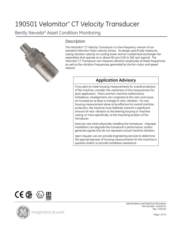
The Velomitor* CT Velocity Transducer is a low-frequency version of our
standard Velomitor Piezo-velocity Sensor. Its design specifically measures
casing vibration velocity on cooling tower and air-cooled heat-exchanger fan
assemblies that operate at or above 90 rpm (100 to 300 rpm typical). The
Velomitor CT Transducer can measure vibration amplitudes at these frequencies
as well as the vibration frequencies generated by the fan motor and speed
reducer.
Application Advisory
If you plan to make housing measurements for overall protection
of the machine, consider the usefulness of the measurement for
each application. Most common machine malfunctions
(imbalance, misalignment, etc.) originate at the rotor and cause
an increase (or at least a change) in rotor vibration. For any
housing measurement alone to be effective for overall machine
protection, the machine must faithfully transmit a significant
amount of rotor vibration to the bearing housing or machine
casing, or more specifically, to the mounting location of the
transducer.
Exercise care when physically installing the transducer. Improper
installation can degrade the transducer’s performance, and/or
generate signals that do not represent actual machine vibration.
Upon request, we can provide engineering services to determine
the appropriateness of housing measurements for the machine in
question and/or to provide installation assistance.
Specifications and Ordering Information
Part Number 141636-01
Rev. Y (05/14)
Page 1 of 13
Specifications
Parameters are specified from +20 °C to +30 °C (+68
°F to +86 °F) and 100 Hz unless otherwise indicated.
Note:
Operation outside the specified limits will result in false
readings or loss of machine monitoring.
Electrical
Dynamic
Output
Impedance
<400 Ω typical
Broadband
Noise Floor (1.5
Hz to 1 kHz)
0.229 mm/s (0.009 in/s) pk. See
Figure 6 for typical noise floor.
Sensitivity
3.94 mV/mm/s (100 mV/in/s) ±5%.
Frequency
Response
3.0 Hz to 900 Hz (180 to 54,000
cpm) ±1.0 dB
1.5 Hz to 1.0 kHz (90 to 60,000
cpm) ±3.0 dB
Temperature
Sensitivity
-8% to +5% typical over the
operating temperature range.
Base Strain
Sensitivity
0.43 mm/s/μstrain (0.017
in/s/μstrain).
Grounding
Internal electronics are isolated
from case.
Maximum Cable
Length
305 metres (1,000 feet) of cable
(part number 02173006) with no
degradation of signal. Note:
Maximum continuous length of
cable available is 300 feet. If
longer lengths are required they
must be spliced or have a
connector installed on them.
Velocity Range
63.5 mm/s pk (2.5 in/s pk) (see
Figure 4 and Figure 5). Vibration
components in excess of 10g pk
above 1 kHz can significantly
reduce this range.
Hazardous Area Approvals
Transverse
Response
Multiple approvals for hazardous
areas certified by Canadian
Standards Association
(CSA/NRTL/C) in North America
and by LCIE in Europe.
Less than 5% of the axial
sensitivity.
Amplitude
Linearity
±2% to 63.5 mm/s pk (2.5 in/s pk)
North America:
9 kHz, minimum (stud mounted,
except quick disconnect)
Ex ia/AEx ia IIC T4
Class I, Div 1 Groups A, B, C & D
Class II, Groups E, F, and G
Class III
When installed per dwg 167536
T4 @ -40°C ≤ Ta ≤ 100°C
10.1 Vdc ± 1.0 Vdc , Pin A
referenced to Pin B
Ex nL/AEx nA IIC T4
Class I, Div 2 Groups A, B, C & D
When installed per dwg 167536
T4 @ -40°C ≤ Ta ≤ 100°C
Mounted
Resonant
Frequency
Output Bias
Voltage
Specifications and Ordering Information
Part Number 141636-01
Rev. Y (05/14)
Page 2 of 13
Shock Limit
ATEX:
5000 g pk, maximum.
II 1 G
Ex ia IIC T4 Ga
T4 @ -40°C ≤ Ta ≤ 100°C
II 3 G
Ex nA IIC T4 Gc
T4 @ -40°C ≤ Ta ≤ 100°C
IECEx
Ex ia IIC T4 Ga
Ex nA IIC T4 Gc
T4 @ -40°C ≤ Ta ≤ 100°C
Brazil:
Ex ia IIC T4 Ga
-40 ºC ≤ Ta ≤ +100 ºC
Ex nA IIC T4 Gc
-55 ºC ≤ Ta ≤ +121 ºC
For further certification and approvals information please visit the
following web site:
Humidity Limit
100% condensing,
non-submerged.
Magnetic Field
Susceptibility
<0.0068 mm/s/gauss (0.268
mil/s/gauss) @ 50 gauss, 50-60Hz
Mechanical
Weight
<297 g (10.5 oz.), typical.
Mounting
Surface
33 mm diameter (1.3 in diameter).
Height
82 mm (3.2 in).
Case Material
www.ge-mcs.com/bently
Compliance and Certifications
EMC
Standards:
EN 61000-6-2, Immunity for
Industrial Environments
European Community Directives
EMC 2004/108/EC
316L stainless steel
Connector
2-pin 316L stainless steel MIL-C5015, top.
Mounting
Torque
4.5 N-m ± 0.6 N-m (40 in–lbf ± 5
in-lbf).
For further certification and approvals information please visit the
following web site:
www.ge-mcs.com/bently
Environmental Limits
Operating
Temperature
-40 °C to +85 °C (-40 °F to +185
°F).
Storage
Temperature
-40 °C to +100 °C (-40 °F to +212
°F).
Specifications and Ordering Information
Part Number 141636-01
Rev. Y (05/14)
Page 3 of 13
Polarity
B:
Pin A goes positive with respect to
Pin B when velocity is from base
to top of the transducer.
99
C:
Mounting Angle
Any orientation.
Ordering Information
Velomitor CT Velocity Transducer
190501-AA-BB-CC
A:
Mounting Hardware Option
00
No stud
01
Stud 3/8-in 24 to 3/8-in 24
02
Stud 3/8-in 24 to 1/2-in 20
03
Adhesive Stud 3/8-in 24
04
Stud M6x1 with 3/8-in 24
adapter
05
Adhesive Stud M6x1 with 3/824 adapter
06
Stud 3/8-in 24 to 1/4-in 28
07
Plate Stud 3/8-in 24 to 3/8-in
24
08
Plate Stud 3/8-in 24 to 1/2-in
20
09
Plate Stud 3/8-in 24 to 1/4-in
NPT
10
Plate Stud M6x1 to M6x1with
3/8-in 24 adapter
11
Plate Stud 3/8-in 24 to 1/4-in
28
12
Plate Stud 3/8-in 24 to M8x1
13
Quick disconnect stud
14
Adapter, 3/8-in 24 to 1/4-in 20
15
Adapter, 3/8-in 24 to 5/16-in
18
16
Adapter, 3/8-in 24 to 3/8-in 24
17
Adapter, 3/8-in 24 to 3/8-in 16
18
Adapter, 3/8-in 24 to 1/2-in 13
19
Adapter, 3/8-in 24 to 1/4-in 18
NPT
20
Adapter, 3/8-in 24 to 3/8-in 18
NPT
21
Adapter, 3/8-in 24 to 1/2-in 14
NPT
22
Adapter, 3/8-in 24 to 3/4-in 14
NPT
23
Adapter, 3/8-in 24 to 1.0-in
11.5 NPT
24
Adapter, 3/8-in 24 to 1.25-in
11.5 NPT
Connection Option
00
MIL-C-5015 connection
interface
Unit with included 32 foot
cable
Agency Approval Option
00
No approvals
01
Multiple approvals
02
Multiple approvals
03
Multiple approvals
04
Multiple approvals
Interconnect Cable
CB2W100-AXXX
Description: Connectors: MIL-C 5015, 2 Socket, Splash
Proof, Premium, isolated to blunt cut, Cable: 20 AWG,
twisted pair, shielded, yellow Teflon® jacket. LOCKING
RING, ADAPTER SEAL, AND O-RING ARE INCLUDED.
A:
Length
015
032
064
112
125
150
200
15 feet (4.57 metres)
32 feet (9.75 metres)
64 feet (19.5 metres)
112 feet (34.1 metres)
125 feet (38.1 metres)
150 feet (45.7 metres)
200 feet (61.0 metres)
Accessories
125389-01
Velomitor CT Manual
128608-02
1.2-in NPT conduit adapter
04284020-01
Adhesive mount base kit. The
adhesive mount base kit design is
for machines with thin casings
that do not permit drilling and
tapping a mounting hole. Kit
contains material (adhesive and
bases) for 2 each 3/8-in 24 UNF
adhesive-mount bases. One kit
can outfit 2 Velomitor CT
Transducers.
Spare Mounting Adapters
All mounting adapters are made from 300 series
stainless steel.
Specifications and Ordering Information
Part Number 141636-01
Rev. Y (05/14)
Page 4 of 13
128689-01
Standard Studs
04365657
3/8-in 24 to 1¾-in 16 quick
disconnect stud base. Attached
to the machine.
3/8-in 24 to 3/8-in 24 stud
87910-01
43055-01
3/8-in 24 to 1/2-in 20 stud
1¾-in 16 mounting base nut.
Interface between stud base and
transducer piece.
87931-01
M6x1 to M6x1 metric stud
(requires metric adapter)
128690-01
3/8-in 24 quick disconnect stud
transducer piece. Attached to the
Velomitor CT Transducer.
87055-01
3/8-in 24 to M6x1 metric
adapter
89139-01
3/8-in 24 to 1/4-in 28 stud
Fittings
Conduit fittings allow connection of flexible, metal,
liquid-tight conduit or armor to the conduit adapter.
03839201
Hex Plate Studs
107756-01
1/2-in NPT straight male conduit
fitting. For connecting flexible,
liquid-tight conduit to the conduit
adapter or a weatherproof
enclosure.
3/8-in 24 to 3/8-in 24 plate stud
107755-01
3/8-in 24 to 1/2-in 20 plate stud
03850000
107754-01
1/2-in NPT straight, male
compression-type fitting. For
connecting Teflon-coated 3/8-in
stainless steel armor to the
transducer or a weatherproof
enclosure. Fitting will fit Teflon®coated armor with a maximum
outer diameter of 13.8 mm (0.543
in) (including Teflon thickness).
3/8-in 24 to 1/4-in NPT plate
stud
107757-01
M6x1 to M6x1 plate stud
(requires metric adapter)
125094-01
3/8-in 24 to M8x1 metric plate
stud
128038-01
3/8-in 24 to 1/4-in 28 Plate Stud
Quick Disconnect Components
The following three components are included with
the quick disconnect mounting option for the
Velomitor CT Transducer. The quick disconnect
option allows you to remove the transducer without
rotating it, allowing you to keep the cable connected
to the transducer.
Teflon®-Coated Stainless Steel Armor
106924-AXX
Note:
A:
This part includes the Teflon-coated armor but not the
cable. You will require 2 1/2-in NPT compression fittings
(part number 03850000) to attach the armor to the
conduit adapter and terminate it at an enclosure.
Armor Length Option in Feet
Order in increments of 10 ft (3.0
m)
Minimum Length: 10 ft (3.0 m)
Maximum Length: 60 ft (18.3 m)
Specifications and Ordering Information
Part Number 141636-01
Rev. Y (05/14)
Page 5 of 13
Flexible Metal Conduit
14847-AXX
A:
Flexible Conduit Length Option in Feet
Order in increments of 1 ft (0.3 m)
Minimum Length: 01 ft (0.3 m)
Maximum Length: 99 ft (30.2 m)
106769-01
Terminal housing. Provides a convenient interface
between the transducer signal cable and monitor
signal cable.
Specifications and Ordering Information
Part Number 141636-01
Rev. Y (05/14)
Page 6 of 13
Dimensional Drawings
Note: All dimensions shown are in millimeters (inches) unless noted otherwise.
1
3
2
4
VELOMITOR
CT
VELOMITOR
CT
5
6
7
1.
1/2” NPT x 12.2 DP (1/2” NPT x 0.48 DP)
2.
35.6 (1.40) diameter
3.
Cable (not included)
4.
Conduit adaptor P/N 128608-02 (not included)
5.
31.8 (1.25) hex flat
6.
31.5 (1.24) diameter
7.
3/8-24 UNF X 8.9 DP (3/8-24 UNF X 0.35 DP)
Figure 1: Velomitor CT Outline Drawing
Specifications and Ordering Information
Part Number 141636-01
Rev. Y (05/14)
Page 7 of 13
Spare Mounting Adapters (Illustrations shown are not to scale)
Notes: All mounting adapters are made from 300 series stainless steel.
Table 1: Standard Studs
Part Number
Size
04365657
3/8-24 to 3/8-24
87055-01
3/8-24 to M6X1
87910-01
3/8-24 to 1/2-20
87931-01
M6X1 to M6X1
89139-01
3/8-24 to 1/4-28
Illustration
Table 2: Adhesive Studs
Part Number
Size
04284020
3/8-24
Illustration
Table 3: 1-3/8 Hex Plate Studs
Part Number
Size
107754-01
3/8-24 UNF to 1/4 NPT
107755-01
3/8-24 UNF to 1/2-20 UNF
107756-01
3/8-24 to 3/8-24
197757-01
M6X1 to M6X1
125094-01
3/8-24 UNF to M8X1
128038-01
3/8-24 UNF to 1/4-28 UNF
Illustration
Specifications and Ordering Information
Part Number 141636-01
Rev. Y (05/14)
Page 8 of 13
Table 4: Quick Disconnect Studs
Part Number
Description
43055-01
Union Mounting Base Nut
128689-01
Quick Disconnect Stud Base
128690-01
Quick Disconnect Transducer
Piece
Illustration
Specifications and Ordering Information
Part Number 141636-01
Rev. Y (05/14)
Page 9 of 13
Graphs
Figure 2: Typical Phase Response
4
Amplitude Response
(dB, Relative to 100 Hz)
3
2
1
0
-1
-2
-3
-4
1
10
100
1000
10000
Frequency (Hz)
Figure 3: Typical Amplitude Response
Specifications and Ordering Information
Part Number 141636-01
Rev. Y (05/14)
Page 10 of 13
2
1
3
1.
Velocity axis (mm/s peak-peak)
2.
Displacement axis (mm peak-peak)
3.
Acceleration axis (m/s2 peak-peak)
Figure 4: Operating Range for Metric Units
Specifications and Ordering Information
Part Number 141636-01
Rev. Y (05/14)
Page 11 of 13
2
1
3
1.
Velocity axis (in./s peak-peak)
2.
Displacement axis (in. peak-peak)
3.
Acceleration axis (g peak-peak)
Figure 5: Operating Range for English Units
Specifications and Ordering Information
Part Number 141636-01
Rev. Y (05/14)
Page 12 of 13
0.050
Amplitude (in/s pk)
0.040
0.030
0.020
0.010
0.000
0
2
4
6
8
10
Frequency (Hz)
Figure 6: Typical Low Frequency Noise Floor
* denotes trademarks of Bently Nevada, Inc., a wholly owned subsidiary of General Electric Company.
Teflon is a trademark of E.I. duPont de Nemours & Company, Inc.
© 2000-2014. Bently Nevada, Inc. All rights reserved
Printed in USA. Uncontrolled when transmitted electronically.
1631 Bently Parkway South, Minden, Nevada USA 89423
Phone: 775.782.3611
Fax: 775.215.2873
http://www.ge-mcs.com/bently
Specifications and Ordering Information
Part Number 141636-01
Rev. Y (05/14)
Page 13 of 13


