Installation Instructions
advertisement
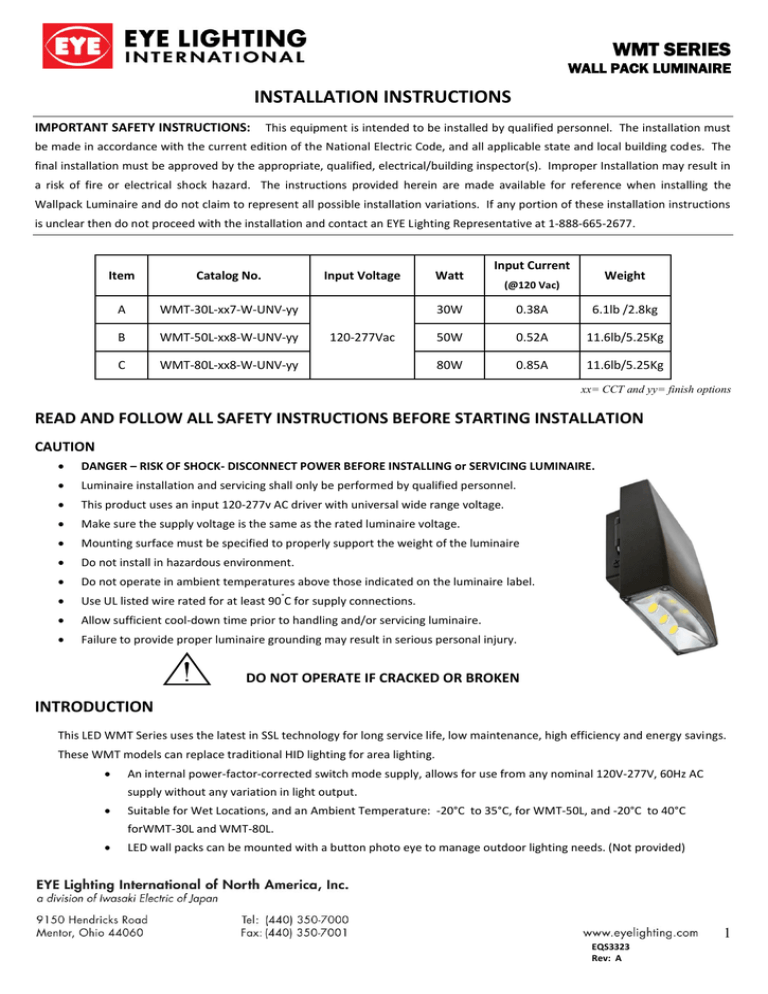
WMT SERIES WALL PACK LUMINAIRE INSTALLATION INSTRUCTIONS IMPORTANT SAFETY INSTRUCTIONS: This equipment is intended to be installed by qualified personnel. The installation must be made in accordance with the current edition of the National Electric Code, and all applicable state and local building codes. The final installation must be approved by the appropriate, qualified, electrical/building inspector(s). Improper Installation may result in a risk of fire or electrical shock hazard. The instructions provided herein are made available for reference when installing the Wallpack Luminaire and do not claim to represent all possible installation variations. If any portion of these installation instructions is unclear then do not proceed with the installation and contact an EYE Lighting Representative at 1-888-665-2677. Item Catalog No. Input Voltage A WMT-30L-xx7-W-UNV-yy B WMT-50L-xx8-W-UNV-yy C WMT-80L-xx8-W-UNV-yy 120-277Vac Watt Input Current Weight (@120 Vac) 30W 0.38A 6.1lb /2.8kg 50W 0.52A 11.6lb/5.25Kg 80W 0.85A 11.6lb/5.25Kg xx= CCT and yy= finish options READ AND FOLLOW ALL SAFETY INSTRUCTIONS BEFORE STARTING INSTALLATION CAUTION DANGER – RISK OF SHOCK- DISCONNECT POWER BEFORE INSTALLING or SERVICING LUMINAIRE. Luminaire installation and servicing shall only be performed by qualified personnel. This product uses an input 120-277v AC driver with universal wide range voltage. Make sure the supply voltage is the same as the rated luminaire voltage. Mounting surface must be specified to properly support the weight of the luminaire Do not install in hazardous environment. Do not operate in ambient temperatures above those indicated on the luminaire label. Use UL listed wire rated for at least 90 C for supply connections. Allow sufficient cool-down time prior to handling and/or servicing luminaire. Failure to provide proper luminaire grounding may result in serious personal injury. ° DO NOT OPERATE IF CRACKED OR BROKEN INTRODUCTION This LED WMT Series uses the latest in SSL technology for long service life, low maintenance, high efficiency and energy savings. These WMT models can replace traditional HID lighting for area lighting. An internal power-factor-corrected switch mode supply, allows for use from any nominal 120V-277V, 60Hz AC supply without any variation in light output. Suitable for Wet Locations, and an Ambient Temperature: -20°C to 35°C, for WMT-50L, and -20°C to 40°C forWMT-30L and WMT-80L. LED wall packs can be mounted with a button photo eye to manage outdoor lighting needs. (Not provided) 1 EQS3323 Rev: A Tools and Materials required: Installation is completed using ordinary tools including: #2 Phillips Screwdriver or Socket head Screwdriver Mounting Hardware (provided by others) Silicone Tube (provided by others) Install Instructions: Notes: Inspect luminaire for defects prior to installation. If defects are noticed then do not install and contact the manufacture immediately. Confirm junction box size PRIOR to removing the gasket material for the desired application. ONLY remove the gasket material needed for the installation. STEP 1: Starting Installation Ensure supply power is turned off. Open the luminaire wiring compartment using a Phillips screw driver (Fig.1.). [WALL] Position back box to mounting surface, level, and mark mounting holes onto surface Refer to Fig. 2 for hole pattern dimensions. Use chosen hardware, level and secure luminaire to the mounting surface. [J-BOX] If mounting to junction box, align back box openings to junction box threaded screw holes. Level and secure the luminaire to junction box with chosen hardware. Ensure luminaire is installed tight to mounting surface. STEP 2: Make Electrical Connections With power turned off, strip wires length as defined by wire nut manufacture. Straighten wires and align frayed strands, insert into wire nut, then twist clockwise until tight. Perform a visual inspection of connections and perform a luminaire light up test. STEP 3: Finishing Installation When light up test is complete, finish installation by placing a bead of silicone to rain seal the top and sides seam between the mounting surface and back box. Then close luminaire wiring compartment using a Phillips screw driver (Fig.3.) and make sure wiring is not pinched. Tighten screw until sections are sealed. a FIG.1 FIG.2 FIG.3 WIRING INSTRUCTIONS Connect the luminaire AC cord to a UL listed junction box with UL listed wire nuts on terminal block per the following: ▪ Black wire: Line (AC L) ▪ White wire: Neutral Wire (AC N) ▪ Green wire: Ground (GND) FIG.4 Wiring Diagram 2 EQS3323
