ULTRAFAST LASERS: Advanced synchronization - Spectra
advertisement

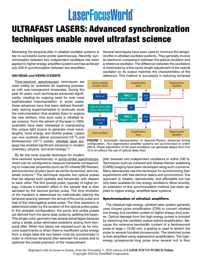
ULTRAFAST LASERS: Advanced synchronization techniques enable novel ultrafast science Minimizing the temporal jitter in ultrafast oscillator systems is key to successful pump-probe spectroscopy. Recently, synchronization between two independent oscillators has been applied to higher-energy, amplified systems and has achieved sub-200 fs synchronization between two amplifiers. IAN READ and KEVIN O’KEEFE Time-resolved spectroscopic techniques are used widely by scientists for exploring processes with sub-nanosecond timescales. During the past 20 years, such techniques advanced significantly, creating an ongoing need for ever more sophisticated instrumentation. In some cases, these advances have first been defined theoretically, leaving experimentalists to anxiously await the instrumentation that enables them to explore the new territory. One such case is ultrafast laser science. From the advent of the laser in 1950, scientists have been interested in manipulating this unique light source to generate more wavelengths, more energy, and shorter pulses. Lasers can now routinely deliver picosecond (10-12) and femtosecond (10-15) pulses. Ultrafast laser science has enabled significant advances in modern chemistry, physics, and even biology1-3. Several techniques have been used to minimize the temporal jitter in ultrafast oscillator systems. They generally involve an electronic comparison between the optical oscillator and a reference oscillator. The difference between the oscillators is minimized by a fine cavity length adjustment of the optical oscillator so its output matches the characteristics of the reference. This method is successful in reducing temporal Seed oscillator (master clock) MHz ref Lock-to-clock with phase adjustment MHz ref +Δφ Seed oscillator Amplification laser TDG 1 “synch” mode Regenerative amplifier kHz ref Δt TDG 2 “trigger” mode kHz ref Amplification laser Regenerative amplifier FIGURE 1. Schematic representation of Spectra-Physics advanced timing configuration. Two regenerative amplifier systems are synchronized to within 200 fs. Phase adjustment of the seed oscillators can generate delays from 0 to 12.5 ns without the use of optical delay lines. By far the most popular technique for modern time-resolved spectroscopy is pump-probe spectroscopy, which can be configured to measure transients corresponding to molecular properties (such as 2D infrared [IR] Raman), semiconductor physics (such as carrier dynamics), and materials science.4 The technique requires two optical pulses that are aligned both spatially and temporally with respect to each other. The first (pump) pulse, typically of higher energy, induces a transient effect in the sample that is then sampled by the second (probe) pulse. The time evolution of the transient is determined by methodically altering the temporal spacing between the arrival of the pump pulse and that of the interrogating probe pulse. The time resolution is determined solely by the duration of the optical probe pulse. In the simplest configuration, the pump and probe pulses are derived from the same laser pulse by splitting the beam. This single-color geometry has several advantages because using a single pulse eliminates problems arising from temporal jitter. When two lasers are required-such as for twocolor experiments or when there is insufficient pulse energy from a single laser-the two lasers must be synchronized in order to minimize temporal jitter between the pulses and to optimize the overall precision of the measurement. jitter between two independent oscillators to within 200 fs. Techniques such as coherent anti-Stokes Raman scattering (CARS) imaging have been developed using such a scheme. Many laboratories use this technique for synchronizing their experiments with free electron lasers and synchrotrons. The approach is reliable, reproducible, and affordable but has only been available for low energy oscillators. More recently, an extension of this synchronization method has been applied to higher energy, amplified laser systems. Synchronization of ultrafast amplifiers The classical high-energy, ultrafast laser system generally uses chirped pulse amplification (CPA) to convert ultrafast low energy (nJ) oscillator pulses to higher energy (mJ) pulses. Optical damage from the high-energy pulses is avoided by stretching the oscillator pulses before amplification. Because the extensive bandwidth content of a femtosecond pulse is large (~10-60 nm), a grating is used to stretch the pulse to several hundred picoseconds. The stretched pulse is then amplified using regenerative amplification. The highenergy picoseconds-long pulse (now several mJ) is then Reprinted with revisions to format, from the November 1, 2010 edition of LASER FOCUS WORLD Online Copyright 2010 by PennWell Corporation compressed back to its original pulsewidth. The CPA process requires several laser sources to operate in synchrony: the seed laser, used to generate the ultrafast pulse; the amplification pump laser, used to power the amplification stage; and the amplifier. Timing of these components has traditionally been handled using an analog electronics module that controls the amplifier switches (Pockels cells). These switches and the amplification laser are synchronized while the seed laser operates in a “free-running” mode. Although operating in this manner is satisfactory for many applications, a limitation arises when high-precision measurements are required. A mismatch exists between the seed laser and amplification laser repetition frequencies so the amplifier system timing varies as a function of this mismatch. For a seed oscillator running at 80 MHz, the overall system timing uncertainty will have an upper limit of 12.5 ns. To overcome this limit, each component of the amplifier system must be synchronized. More sophisticated, digital synchronization modules such as the Spectra-Physics Timing and Delay Generator (TDG) improve precision and allow Chirped pulse Waveplate Polarizer Spitfire Mai Tai AOPDF Spitfire Pro Spitfire triggered externally from Spitfire Pro Pockel cell to achieve synchronization Driving pulse HHG target chamber Fig. 1). When two seed lasers are used, the relative arrival of each amplifier pulse can be adjusted from t = 0 to t = tmax, where tmax is equivalent to the seed laser interpulse spacing. This adjustment is accomplished via electronic phase adjustment of the seed laser arrival time. The timing electronics (TDG1, TDG2) control the additional amplifier components. In practice, several experimental methods can be performed that benefit from this advance. A popular example of where this capability is utilized is high harmonic generation (HHG) via quasi-phase matching (QPM). High harmonic generation When generated using femtosecond lasers, HHG suffers from very low conversion efficiency. Typical conversion efficiencies are on the order of 10-6 for photon energies of 100 eV, with the conversion efficiency decreasing to as little as 10-15 for photon energies near 1 keV. One reason for such low conversion efficiencies is the difference between the phase velocities of the driving laser and the harmonic beam. This causes the intensity of each generated harmonic to oscillate with propagation distance. The oscillation period is 2Lc, where Lc = π/Δk. Here, Lc is the coherence length, and Δk is the wave vector mismatch. In order to overcome this problem, the harmonic generation must be phase matched such that Δk = 0. This can be achieved for output photon energies up to approximately 100 eV by balancing different sources of dispersion in a gas-filled hollow-core waveguide. However, above a certain ionization level it is no longer possible to balance the negative dispersion caused by plasma formed during ionization, and alternative approaches to phase matching are required. Quasi-phase matching is an alternative approach suitable for increasing the generation efficiency of higher-order harmonics. The aim of QPM is to suppress HHG in those regions where the generated harmonics are out of phase with XUV spectrometer the harmonic beam. If HHG can be suppressed in N such out-of-phase regions, then the overall FIGURE 2. Experimental setup for quasi-phase matching. Two amplifier intensity of the harmonic beam should increase systems operate in synchrony through use of the scheme outlined in Fig. 1. by a factor N2, greatly increasing the efficiency of The chirped output pulse is passed through a waveplate polarizer to generate this source. This increase can be achieved using a pulse train. The characteristics of the output pulse train can be programmed a counter-propagating train of femtosecond laser using an acousto-optic programmable dispersive filter (AOPDF) to maximize harmonic generation. pulses. In pulse-train QPM, harmonic generation is suppressed in regions where the driving laser pulse overlaps with a counter-propagating pulse. This interfor multiple amplifier systems to be synchronized. action modifies the trajectory of the photoionized electron. To date, pulse trains containing just a few pulses have been Digital Synchronization used with this technique. For QPM to be most efficient, a During the past few years, digital equipment has been de- large number of high-energy counter-propagating pulses veloped for improving the overall timing capabilities of CPA must be generated and their relative temporal separation laser systems. Digital electronics enable the timing of the must be controlled. switching electronics to be governed by the seed laser. By In the simplest configuration, a single amplifier source can dividing the 80 MHz signal from the seed laser to about 1 be used where a single, high-energy output pulse is split kHz, additional amplifier systems can be synchronized to into two parts. The first part is used, untreated, to generate either one or multiple seed lasers to within <200 fs (see the harmonics, while the second part generates the counter-propagating pulse train. This pulse train is produced by first introducing a linear chirp onto the femtosecond pulse. The chirped pulse is then passed through a birefringent plate oriented at 45° relative to the polarization of the incident pulse. Next, a linear polarizer is oriented parallel to the incident pulse. The waveplate/polarizer combination attenuates all wavelength components whose retardance is an odd multiple of π/2; those components whose retardance is a multiple of 2π pass with no attenuation. A pulse train is formed whose spacing is constant and depends upon the thickness of the birefringent plate. An extension of this technique, in which the separation between pulses in the train can be controlled via computer, has also recently been demonstrated and is described below.5 Optimizing pulse trains for efficient HHG This technique for generating pulse trains with variable pulse spacing is of particular interest for QPM because it enables them to be tailored to best match the coherence lengths of harmonics in a waveguide.6 The lengths can change based upon local conditions inside the waveguide. In order to achieve QPM over many coherent zones pulse trains must be generated in which there are large numbers of pulses of sufficient energy that each pulse in the train can suppress harmonic generation, and in which the spacing between the pulses can be controlled to deliver pulse trains with nonlinear pulse spacing. Programmable control of these pulse trains is a major advantage since it allows the most suitable pulse train to be easily synthesized to quasiphase-match a particular harmonic. The first step to achieving this level of control requires that the driving pulse and counter-propagating pulse come from two different amplifier sources and that the amplifier sources are fully synchronized (see Fig. 2). In this configuration, the driving pulse is delivered, untreated, from the first amplifier. The counter-propagating pulse originates from the second amplifier, and its characteristics are controlled using a pulse shaper. Pulse trains with variable pulse spacing can be generated and HHG via QPM can be maximized. Synchronization of the amplifier pulses is critical for QPM in this configuration because the driving and counter-propagating pulses must collide at the same point in the waveguide for each laser shot. The Spectra-Physics Timing and Delay Generator enables a clean and robust approach for achieving sub-200 fs synchronization between two amplifiers at no additional cost. REFERENCES 1. A.H. Zewail, Femtochemistry: Ultrafast Dynamics of the Chemical Bond, World Scientific Series in 20th Century Chemistry, Vol. 3, World Scientific Publishing Co. Pte. Ltd., Singapore (1994). 2. Y. Silberberg, “Ultrafast Physics: Quantum Control with a Twist,” Nature, 430, 624-625 (Aug. 5, 2004). 3. W. Denk, J.H. Strickler, W.W. Webb, “Two-photon laser scanning microscope,” Science, 248, 73-76 (1990). 4. C. Weiman; T.W. Hänsch, Phys. Rev. Lett., 36, 1170 (1976). 5. K. O’Keefe, T. Robinson, and S.M. Hooker, “Genera tion and control of chirped, ultrafast pulse trains,” J. Opt., 12, 015201 (2010). 6. T. Robinson, K. O’Keefe, S.M. Hooker, “Generation and control of ultrafast pulse trains for quasi-phase-match ing high-harmonic generation,” J. OSA B, 27, 763-772 (2010). Ian Read is senior product manager, ultrafast amplifiers for Newport Corp.’s Spectra-Physics Laser Division, 3635 Peterson Way, Santa Clara, CA 95054; e-mail: ian.read@newport.com; www.newport.com. Kevin O’Keefe is senior research associate, Department of Physics, Clarendon Laboratory, University of Oxford, Oxford, England.


