VOL. 11, NO. 6, MARCH 2016
ISSN 1819-6608
ARPN Journal of Engineering and Applied Sciences
©2006-2016 Asian Research Publishing Network (ARPN). All rights reserved.
www.arpnjournals.com
COMPARATIVE STUDY OF SWITCHABLE FILTERS AND A NEW
TECHNIQUE OF BANDSTOP TO BANDPASS FILTER
USING LOSSY RESONATORS
M. K. Zahari1, B. H. Ahmad1, P. W. Wong2 and N. A. Shairi1
1
Microwave Research Group, Centre for Telecommunication Research and Innovation, Universiti Teknikal Malaysia Melaka, Durian
Tunggal, Melaka, Malaysia
2
Electrical and Electronic Engineering Department, Universiti Teknologi Petronas, Bandar Seri Iskandar, Tronoh, Perak, Malaysia
E-Mail: khairyzahari@hotmail.com
ABSTRACT
In this paper, the comparative studies of switchable bandstop to bandpass (or bandpass to bandstop) are presented.
It shows that by using microstrip technology, high-Q bandstop to bandpass responses is difficult to achieve. Therefore, this
paper proposes a new technique of matched bandstop to bandpass filter using two lossy low-Q resonators. The proposed
technique is implemented based on perfectly-matched bandstop topology which is not only produced high-Q bandstop
filter, but also easy to switch from bandstop to bandpass response. The PIN diodes (as switching element) that used in this
proposed technique are incorporated into the topology to exhibit either matched bandstop response or bandpass response
by turning “ON” and “OFF” of the PIN diodes. The proposed technique based on simulation result was carried out. As a
result, it was found that the proposed technique was able to switch the microstrip filter from matched bandstop to bandpass
filter using two lossy low-Q resonators.
Keywords: switchable filter, lossy resonator, bandstop filter, bandpass filter.
INTRODUCTION
There have been widely developed switchable
bandstop to bandpass (or bandpass to bandstop) filter for
wireless communication and cognitive radio system.
For example, in a cognitive radio environment, this filter is
used in the radio system to select signals of interest or
attenuate
interfering
signals.
It depends on
the
environment or mode of operation of the radio. In
(Zhengzheng et al., 2011), a reconfigurable and
cognitive radio requires frequency agile radio front-end
modules to cover a wide range of wireless communication
spectrum. Therefore, switchable filters are very important
components in cognitive radios and have been focusing on
recent research and development (Rebeiz et al., 2009),
(Abunjaileh et al. 2010), (Adoum et al., 2012), (Naglich et
al., 2012), (Anand et al., 2013), (Juseop et al., 2013),
(Śnchez-Soriano et al., 2013), Pu-Hua et al., 2014),
(Rabbi et al., 2014), (Young and Rebeiz, 2014), (Adoum
et al., 2014).
In this paper, the comparative study of switchable
bandstop to bandpass (or bandpass to bandstop) is
discussed and a new technique of switchable filter with the
ability to switch between matched bandstop to bandpass
filter based on lossy resonator is proposed. The proposed
switchable filter was designed using microstrip
technology. The switchable bandstop to bandpass filter
response using low-Q lossy resonator was investigated
based on simulated results. The switchable filter was
realized on L-shape matched bandstop filter (which is a
lossy resonator). PIN diodes or varactor diodes were used
to control the switching operation between bandstop and
bandpass response.
COMPARATIVE STUDY OF SWITCHABLE
BANDSTOP TO BANDPASS FILTER
Introduction of switchable filter
There are a few studies on bandpass-to-bandstop
(or bandstop-to-bandpass) filter that have been reported. In
paper (Yi-Ming et al., 2009), the author demonstrated a
bandpass-to-bandstop filter with a closed-ring resonator,
where reconfigurability results from the perturbation effect
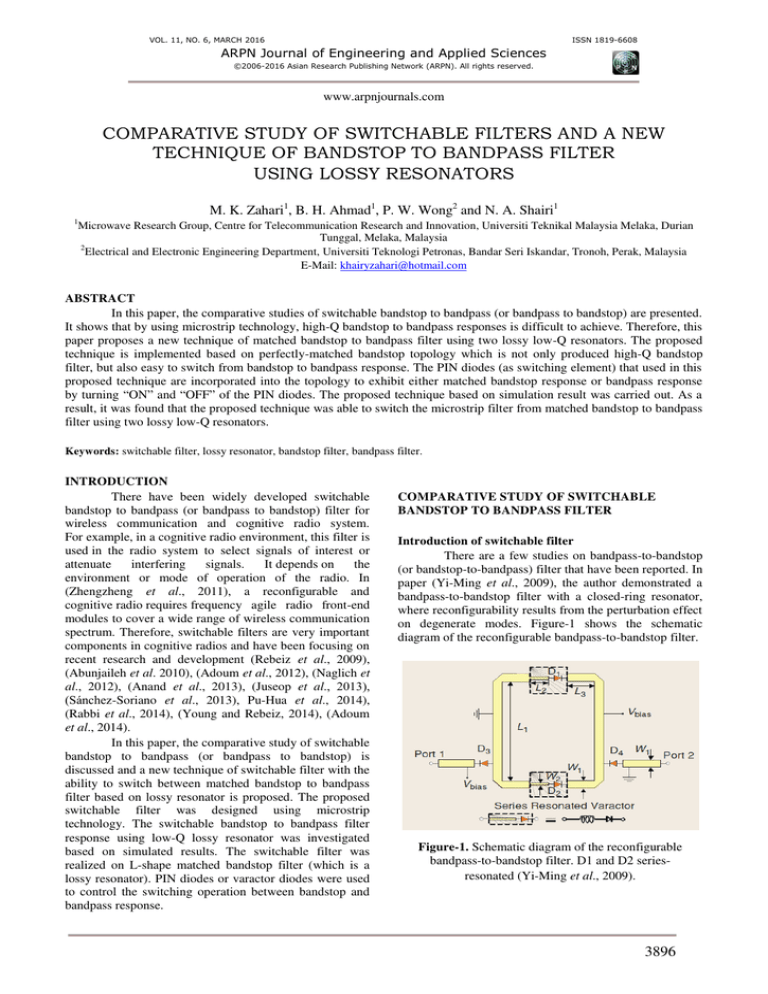
on degenerate modes. Figure-1 shows the schematic
diagram of the reconfigurable bandpass-to-bandstop filter.
Figure-1. Schematic diagram of the reconfigurable
bandpass-to-bandstop filter. D1 and D2 seriesresonated (Yi-Ming et al., 2009).
3896
VOL. 11, NO. 6, MARCH 2016
ISSN 1819-6608
ARPN Journal of Engineering and Applied Sciences
©2006-2016 Asian Research Publishing Network (ARPN). All rights reserved.
www.arpnjournals.com
The filter consisted of one-wavelength closedring resonator with series-resonated varactors D1 and D2.
The filter then connected at the symmetry plane with the
coupling varactors D3 and D4 which are connected at the
input and output ports respectively. By appropriately
controlling the D1 and D2 reactance, bandpass or bandstop
filter can be achieved.
The simulated and measured results of the
reconfigurable bandpass-bandstop filter are shown in
Figure-2. The bandpass and bandstop states are
reconfigured based on the varactor bias voltage. The
bandpass response is achieved when the bias voltage is at
5.5 V, and the simulated insertion loss is 0.5 dB at 2.45
GHz, the 3-dB bandwidth is 360 MHz, and two
transmission zeros exist at 2.2 GHz and 3.2 GHz,
respectively. Bandstop response is achieved when bias
voltage is at 0 V and has 20 dB rejection frequencies of
2.4-2.7 GHz.
Figure-2. Simulated and measured results of the reconfigurable bandpass-to-bandstop
filter at 2.45 GHz, (a) Bandpass state, (b) Bandstop state (Yi-Ming et al., 2009).
A novel reconfigurable switched bandpass to
bandstop filter using electromagnetic bandgap structures
(EBG) at the same frequency has been reported in (Karim
et al., 2006). The authors derive the unit model for the
reconfigurable filter by using an equivalent circuit
approach and full wave electromagnetic simulation for
extracting the values of the lumped elements. The
Dispersion characteristics are obtained by using a
Floquet’s theorem to analyze the behavior within the unit
cell. PIN diode is used to switch bandpass to bandstop
filter where the unit cells are cascaded to form a bandpass
filter. Figure-3 shows the fabricated structure of the
reconfigurable filter.
Figure-3. Fabricated structure of the reconfigurable filter
(Karim et al., 2006).
Figure-4 shows the measurement result. It shows
that when the diode is off, a band pass filter is operating at
7.3 GHz with an insertion loss of 2.1 dB. It has 3 dB
bandwidth of 5.2 GHz and rejection greater than 35 dB.
When the diode is switched ON, it will show a bandstop
response. The measurement results for a bandstop show
the resonant frequency at 7.3 GHz and it has insertion loss
of 1.6 dB. The 20 dB rejection bandwidth is 5.3 GHz
(Karim et al., 2006).
Figure-4. Measurement results of the reconfigurable filter
(a) PIN diode is 'OFF', bandpass filter (b) PIN diodes is
'ON', bandstop filter (Karim et al., 2006).
3897
VOL. 11, NO. 6, MARCH 2016
ISSN 1819-6608
ARPN Journal of Engineering and Applied Sciences
©2006-2016 Asian Research Publishing Network (ARPN). All rights reserved.
www.arpnjournals.com
A tunable bandstop-to-bandpass filter with
reconfigurable 2- and 4-pole responses have been reported
by Young and Rebeiz (2014). The filter performances are
achieved based on the change of the coupling paths using
the zero-valued couplings. In this filter, the authors state
that a coupled line with series capacitor is employed to
obtain the zero-valued coupling between the adjacent
resonators. Figure-5 shows the fabricated of the filter.
Figure-6. Measured S21 responses for (a) 2-pole (b) 4-pole
bandstop modes (Young and Rebeiz, 2014).
Figure-5. The fabricated filter for 2-pole and 4-pole
responses (Young and Rebeiz, 2014).
Figure-6 shows measured result of S21 bandstop
response. As shown in Figure-6(a), the 2-pole bandstop
rejection level and the 20-dB bandwidth are measured as
24-28 dB and 15-24 MHz for center frequencies of 0.640.96 GHz. On the other hand, the rejection level and the
20-dB bandwidth for the 4-pole bandstop mode are 32-41
dB and 25-45 MHz, respectively, for center frequencies of
0.71-0.96 GHz as shown in Figure-6(b).
Figure-7 shows the measured center frequency
for bandpass modes. The 2-pole bandpass mode covers
0.71–0.99 GHz with an insertion loss and 1-dB bandwidth
of 4.9–2.9 dB and 34-63 MHz, respectively. The 4-pole
bandpass mode covers 0.72-1.01 GHz with an insertion
loss and 1-dB bandwidth of 6.1–4.8 dB and 41-70 MHz,
respectively. The 2-pole bandpass mode has 1.2 dB better
insertion loss compared to the 4-pole filter at almost the
same bandwidths.
Figure-7. Measure S21 responses for (a) 2-pole bandpass
mode, (b) 4-pole bandpass mode (Young and
Rebeiz, 2014).
3898
VOL. 11, NO. 6, MARCH 2016
ISSN 1819-6608
ARPN Journal of Engineering and Applied Sciences
©2006-2016 Asian Research Publishing Network (ARPN). All rights reserved.
www.arpnjournals.com
lossy resonator (Guyette et al., 2005) for switchable highQ bandstop to bandpass with small and compact size.
These will be described and discussed in details in the next
sub-topic.
Table-1 shows the comparative of switchable
bandstop to bandpass (or bandpass to bandstop) in term of
technique and insertion loss S . Based on these
literatures, it is found that there is a potential study on the
Table-1. Comparative of technique and insertion loss (S21).
Technique
A closed-ring resonator
(Yi-Ming et al., 2009)
Electromagnetic bandgap structures
(EBG) (Karim et al., 2006)
Reconfigurable 2- and 4-pole
(Young and Rebeiz, 2014)
Bandpass characteristic
�
Bandstop characteristic
�
0.5 dB
> 20 dB
2.1 dB
>35 dB
2-pole: 4.9-2.9 dB
4-pole:6.1-4.8 dB
2-pole: > 20 dB (24-28 dB)
4-pole: >20 dB (32-41 dB)
SWITCHABLE MATCHED BANDSTOP TO
BANDPASS FILTER USING LOSSY RESONATOR
Introduction of matched bandstop filter
In 2005, (Guyette et al., 2005) were successfully
demonstrated an ideal infinite stopband attenuation of the
matched bandstop where high notch depth and selectivity
can be produced with only two lossy low-Q resonators in
microstrip technology. This idea was from (Jachowski,
2004) that builds upon the perfectly-notch concept where
it consists of two identical lossy resonators connected to
the 90° hybrid coupler or directional coupler as shown in
Figure-8. This technique enables the use of two low-Q
lossy resonators for high attenuation of bandstop filter
applications. Thus, its advantages are not only to produce
higher stopband attenuation but also being perfectly
matched in the passband and stopband as well as compact
in size.
Figure-8. Conceptual diagram of an enhanced Q notch
filter employing a 3-dB, 90° hybrid coupler (Guyette
et al., 2005).
filter (Adoum et al., 2013), (Zahari et al., 2011) (Zahari et
al. 2012) and RF switches (Shairi, et al., 2012) (Shairi, et
al., 2015).
The matched bandstop filter has a characteristic
of Allpass network where an ideal lossless Allpass
network has the property of passing all frequencies with
zero attenuation, and thus must present a perfect match at
all frequencies (Guyette et al., 2009). The perfectly
notched concept (Guyette et al., 2005) was applied to
improve the Q factor of bandstop limiter in the filter
design. Based on a reflection mode filter, this concept
makes use of two identical lossy resonators coupled to a 3dB 90° hybrid coupler with correct coupling factors. At
the center frequencies, the incident signals are critically
coupled to the resonators and absorbed in the resistive part
of the resonator leaving no reflected signals at the output,
thus achieving a theoretically infinite attenuation (Guyette,
2010). Figure-9 shows a practical matched notch filter and
Figure-10 shows the bandstop response of perfectlymatched bandstop filter.
Figure-9. Realization of matched bandstop filter using
two L-shape resonators.
The overview of the matched bandstop filter
using lossy resonators was reported by Shairi, et al.,
(2014), where the lossy resonator was applied in matched
bandstop filter (Guyette et al., 2005), (Jachowski, 2004),
(Guyette et al. 2009), tunable filter (Guyette, 2010),
(Phudpong and Hunter, 2007), (Jachowski and Guyette,
2009), (Peng et al., 2007), switchable bandstop to Allpass
3899
VOL. 11, NO. 6, MARCH 2016
ISSN 1819-6608
ARPN Journal of Engineering and Applied Sciences
©2006-2016 Asian Research Publishing Network (ARPN). All rights reserved.
www.arpnjournals.com
filter provided two modes of operation under two
conditions, where the filter can be switched either matched
bandstop or bandpass response. The switching element
(PIN diodes) in this filter was incorporated into the filter
topology as shown in Figure-12. In the first condition, the
PIN diodes were turned “ON” to produce a matched
bandstop response. During this condition, the PIN diodes
act like a variable resistor � . In the second condition, the
PIN diodes were turned “OFF” to produce a bandpass
response.
Figure-10. Perfectly-matched bandstop response
(Guyette, 2005).
This topology has a symmetrical structure of twoport network defined by utilizing the conventional method
for odd and even mode analysis. Odd and even mode
admittances of the circuit structure depicted below:
=
=
−�� ��
(1)
�� −��
(2)
+��
+��
+��
+��
As stated by (Hunter et al., 2005), if �� = /��
for all frequencies, then | | = for all frequencies, and
the network possesses the Allpass property. If �� = �� at a
certain frequency, then | | = , and the network
produces infinite attenuation at that frequency. Based on
Figure-11, the network consists of two identical resonators
with an unloaded Q of ��/�, and four admittance
inverters. The circuit shown that both Allpass and the
perfect notch property are met when � = ±√ � and
� = �. The power at stopband frequencies is absorbed by
the losses of the present resonators and is not reflected as
in conventional filters.
Figure-11. A coupled-resonator model of a matched
bandstop filter (Guyette et al., 2005).
The proposed of switchable matched bandstop to
bandpass filter
As described above, the proposed of switchable
filter was designed at center frequency of 2.4 GHz. The
Figure-12. Generalized model of switchable matched
bandstop to bandpass filter.
The new switchable filter with the ability to
switch between matched bandstop and bandpass filter is
proposed. It was designed using L-shape lossy resonators
as shown in Figure-13.
Figure-13. The proposed switchable matched bandstop
to bandpass filter.
The PIN diodes as a switching element were
integrated into the L-shape matched bandstop filter to
switch from matched bandstop to bandpass responses.
Figure-14 shows the simulated matched bandstop response
when the PIN diodes were turned “ON”. The simulated
3900
VOL. 11, NO. 6, MARCH 2016
ISSN 1819-6608
ARPN Journal of Engineering and Applied Sciences
©2006-2016 Asian Research Publishing Network (ARPN). All rights reserved.
www.arpnjournals.com
attenuation was 64 dB and the return loss was below than
13 dB. From the simulated result at the center frequencies,
the incident signals were critically coupled to the
resonators and absorbed in the resistive part of the
resonator leaving no reflected signals at the output, thus
achieving a theoretically infinite attenuation (Phudpong,
2009). The filter was having high-Q factor matched
bandstop response while being perfectly matched in both
the passband and stopband (Hunter et al., 2005). In
Figure-15 shows the simulated bandpass response, where
the insertion loss was around 9 dB. Further improvement
of higher insertion loss of the bandpass filter can be done
by enhancing the coupling resonator or tuning the length
of each resonator.
bandstop to bandpass responses. The proposed new
technique of matched bandstop to bandpass filter using
lossy resonators also are reported. By implementing
perfectly-matched bandstop topology in the filter, it is not
only producing high-Q factor of bandstop response, but
also able to switch to bandpass response. Thus, PIN diodes
are incorporated into the topology to exhibit either
matched bandstop or bandpass response by turning “ON”
and “OFF”. The simulated result showed that the matched
bandstop filter can be switched to bandpass. Further
improvement of higher insertion loss of the bandpass filter
can be done by enhancing the coupling resonator or tuning
the length of each resonator. Potential future works will be
focused on the enhancement of the bandpass response and
realized in the fabrication stage for verification.
REFERENCES
Abunjaileh, A.I.; Hunter, I.C., "Tunable Bandpass and
Bandstop Filters Based on Dual-Band Combline
Structures," Microwave Theory and Techniques, IEEE
Transactions on. Vol. 58, no. 12, pp. 3710-3719, Dec.
2010.
A. C. Guyette, I. C. Hunter, R. D. Pollard, D. R.
Jachowski, “Perfectly-Matched Bandstop Filter using
Lossy Resonator”, IEEE MTT-S Int. Microwave Symp.
Dig. pp. 517-520, 2005.
Figure-14. Simulated matched bandstop response.
Adoum, B.A.; Wong Peng Wen; Osman, M.S.,
"Switchable matched band-stop filter for high power
interference
mitigation," Microwave
Conference
Proceedings (APMC), 2013 Asia-Pacific, pp. 19-21, 5-8
Nov. 2013.
Adoum, B.A.; Wong Peng Wen, "Numerical investigation
of novel switchable microwave band-stop to bandpass
filters," Intelligent and Advanced Systems (ICIAS), 5 th
International Conference on. vol., no., pp. 1, 6, 3-5 June
2014
Figure-15. Simulated bandpass response.
Anand, A.; Small, J.; Arif, M.S.; Sinani, M.; Peroulis, D.;
Xiaoguang Liu, "A novel high-Qu octave-tunable
resonator with lumped tuning elements," Microwave
Symposium Digest (IMS), 2013 IEEE MTT-S
International , pp. 1-3, 2-7 June 2013.
The frequency resonance of the bandpass
response can be enhanced by tuning the resonator using
PIN diodes.
D. R. Jachowski, “Passive Enhancement of Resonator Q in
Microwave Notch Filters”, IEEE MTT-S Int. Microwave
Symp. Dig. vol. 3, pp. 1315-1318, 2004.
CONCLUSIONS/FUTURE WORK
In this paper, the comparative study of switchable
bandstop to bandpass (or bandpass to bandstop) and a new
technique of switchable bandstop to bandpass filter are
presented. The comparative study has shown that by using
microstrip technology, it is difficult to achieve high-Q
D. R. Jachowski and A. C. Guyette, “Sub-octave-tunable
notch filter,” IEEE International Symposium on
Electromagnetic Compatibility. pp. 99-102, Aug. 2009
3901
VOL. 11, NO. 6, MARCH 2016
ISSN 1819-6608
ARPN Journal of Engineering and Applied Sciences
©2006-2016 Asian Research Publishing Network (ARPN). All rights reserved.
www.arpnjournals.com
Guyette, A.C.; Hunter, I.C.; Pollard, Roger D.; Jachowski,
Douglas R., "Perfectly-matched bandstop filters using
lossy resonators," in Microwave Symposium Digest, 2005
IEEE MTT-S International , pp. 4, 12-17 June 2005.
Naglich, Eric J.; Juseop Lee; Peroulis, D.; Chappell, W.J.,
"Switchless Tunable Bandstop-to-All-Pass Reconfigurable
Filter," Microwave Theory and Techniques, IEEE
Transactions on. vol. 60, no. 5, pp. 1258-1265, May 2012.
Guyette, A.C.; Hunter, I.C.; Pollard, Roger D., "Design of
absorptive microwave filters using allpass networks in a
parallel-cascade configuration," Microwave Symposium
Digest, 2009. MTT '09. IEEE MTT-S International, pp.
733-736, 7-12 June 2009.
Naglich, Eric J.; Juseop Lee; Peroulis, D.; Chappell, W.J.,
"High-Q tunable bandstop filters with adaptable
bandwidth and pole allocation," Microwave Symposium
Digest (MTT), 2011 IEEE MTT-S International. pp. 1-4,
5-10 June 2011.
Guyette, A.C., "Varactor-tuned bandstop filters with
tunable center frequency and bandwidth," Wireless
Information Technology and Systems (ICWITS), 2010
IEEE International Conference on, pp. 1, 4, Aug. 28 2010Sept. 3 2010.
Peng Wong; Hunter, I.C.; Pollard, Roger D., "Matched
bandstop resonator with tunable K-inverter," Microwave
Conference, 2007. European, pp.664-667, 9-12 Oct. 2007.
I.C.Hunter, A.C. Guyette, R.D. Pollard, Passive
microwave receive filter networks using low-Q resonator,
IEEE Microwave Magazine, 2005.
Juseop Lee; Naglich, E.J.; Sigmarsson, H.H.; Peroulis, D.;
Chappell, W.J., "New Bandstop Filter Circuit Topology
and Its Application to Design of a Bandstop-to-Bandpass
Switchable Filter," Microwave Theory and Techniques,
IEEE Transactions on. vol. 61, no.3, pp. 1114-1123,
March 2013.
Jachowski, D.R., 2010. Tunable lumped-element notch
filter with constant bandwidth. In Wireless Information
Technology and Systems (ICWITS), 2010 IEEE
International Conference on. Ieee, pp. 1-4.
Karim, M.F.; Liu, A.Q.; Alphones, A.; Yu, A.B., "A
Novel
Reconfigurable
Filter
Using
Periodic
Structures," Microwave Symposium Digest, 2006. IEEE
MTT-S International, pp. 943-946, 11-16 June 2006.
N.A. Shairi, B.H. Ahmad, P.W. Wong, Z. Zakaria, "An
Overview of Matched Bandstop Filters using Lossy
Resonators," Aust. J. Basic and Appl. Sci. 8(9): 135-144,
2014.
N. A. Shairi, B. H. Ahmad, M. K. Zahari, P. W. Wong.
"The Potential Application of Switchable Matched
Parallel-Coupled Stub Resonator in SPDT Discrete Switch
Design," 2012 IEEE Asia-Pacific Conference on Applied
Electromagnetics (APACE 2012), pp. 372-376, 2012.
N. A. Shairi, B. H. Ahmad, P. W. Wong, Z. Zakaria, "
High Isolation and Absorptive Feature in Single Pole
Double Throw (SPDT) Discrete Switch Design using
Switchable Matched Ring Resonator," Advanced Science
Letters, 21(1): 93-97, 2015.
Phudpong, P., I.C. Hunter, Nonlinear Matched Reflection
Mode Bandstop Filters for Frequency Selective Limiting
Applications. In Microwave Symposium, 2007.
IEEE/MTT-S International, pp. 1043-1046.
P. Phudpong and I. C. Hunter, “Frequency-selective
limiters using nonlinear bandstop filters,” IEEE Trans.
Microw. Theory Tech. vol. 57, no. 1, pp. 157-164, Jan.
2009.
Pu-Hua Deng; Jen-Tse Tsai; Ren-Chuan Liu, "Design of a
Switchable Microstrip Dual-Band Lowpass-Bandpass
Filter," Microwave and Wireless Components Letters,
IEEE, vol. 24, no. 9, pp. 599-601, Sept. 2014.
Rabbi, K.; Budimir, D., "Highly Selective Reconfigurable
Filter for UWB Systems," Microwave and Wireless
Components Letters, IEEE. vol. 24, no. 3, pp. 146-148,
March 2014.
Rebeiz, G.M.; Entesari, K.; Reines, I.; Park, S.-J.; ElTanani, M.A.; Grichener, A.; Brown, A.R., "Tuning in to
RF MEMS," Microwave Magazine, IEEE , vol. 10, no. 6,
pp. 55-72, Oct.
Śnchez-Soriano, M.A.; Ǵmez-Garća, R.; TorregrosaPenalva, G.; Bronchalo, E., "Reconfigurable-bandwidth
bandpass filter within 10-50%," Microwaves, Antennas &
Propagation, IET. vol. 7, no. 7, pp. 502-509, May 15 2013.
Tsung-Chieh Lee; Juseop Lee; Naglich, E.J.; Peroulis, D.,
"Octave tunable lumped-element notch filter with
resonator
Q-independent
zero
reflection
coefficient," Microwave Symposium (IMS), 2014 IEEE
MTT-S International, pp. 1-4, 1-6 June 2014.
Yi-Ming Chen; Sheng-Fuh Chang; Cheng-Yu Chou; KunHsing Liu, "A reconfigurable bandpass-bandstop filter
based on varactor-loaded closed-ring resonators
[Technical Committee]," Microwave Magazine, IEEE, vol.
10, no. 1, pp. 138-140, February 2009.
3902
VOL. 11, NO. 6, MARCH 2016
ISSN 1819-6608
ARPN Journal of Engineering and Applied Sciences
©2006-2016 Asian Research Publishing Network (ARPN). All rights reserved.
www.arpnjournals.com
Young-Ho Cho; Rebeiz, G.M., "Two- and Four-Pole
Tunable 0.7-1.1-GHz Bandpass-to-Bandstop Filters With
Bandwidth Control," Microwave Theory and Techniques,
IEEE Transactions on, vol. 62, no. 3, pp. 457-463, March
2014.
Young-Ho
Cho;
Rebeiz,
G.M.,
"0.7-1.0-GHz
Reconfigurable
Bandpass-to-Bandstop
Filter
with
Selectable 2- and 4-Pole Responses," Microwave Theory
and Techniques, IEEE Transactions on. vol. 62, no. 11, pp.
2626-2632, Nov. 2014.
Zahari, M.K.; Ahmad, B.H.; Shairi, N.A.; Peng Wen
Wong, "Reconfigurable matched bandstop filter," RF and
Microwave Conference (RFM), 2011 IEEE International,
pp. 230-233, 12-14 Dec. 2011.
Zahari, M.K.; Ahmad, B.H.; Shairi, N.A.; Peng Wen
Wong, "Reconfigurable dual-mode ring resonator matched
bandstop filter," Wireless Technology and Applications
(ISWTA), 2012 IEEE Symposium on. pp. 71-74, 23-26
Sept. 2012.
Zhengzheng Wu; Yonghyun Shim; Rais-Zadeh, M.,
"Switchable wide tuning range bandstop filters for
frequency-agile radios," Electron Devices Meeting
(IEDM), 2011 IEEE International, 5-7 Dec.
3903


