Instruction Sheet 860380690
Issue 4, February 2014
Uniprise® Solutions
www.commscope.com
Optical Cable Entry Facility (OCEF)
Installation Instructions
General
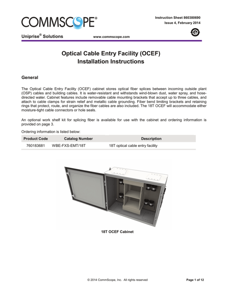
The Optical Cable Entry Facility (OCEF) cabinet stores optical fiber splices between incoming outside plant
(OSP) cables and building cables. It is water-resistant and withstands wind-blown dust, water spray, and hosedirected water. Cabinet features include removable cable mounting brackets that accept up to three cables, and
attach to cable clamps for strain relief and metallic cable grounding. Fiber bend limiting brackets and retaining
rings that protect, route, and organize the fiber cables are also included. The 18T OCEF will accommodate either
moisture-tight cable connectors or hole seals.
An optional work shelf kit for splicing fiber is available for use with the cabinet and ordering information is
provided on page 3.
Ordering information is listed below:
Product Code
760183681
Catalog Number
WBE-FXS-EMT/18T
Description
18T optical cable entry facility
18T OCEF Cabinet
© 2014 CommScope, Inc. All rights reserved
Page 1 of 12
860380690
Instruction Sheet
www.commscope.com
How to Contact Us
•
To find out more about CommScope® products, visit us on the web at http://www.commscope.com/
•
For technical assistance:
-
Within the United States, contact your local account representative or technical support at
1-800-344-0223. Outside the United States, contact your local account representative or
Authorized Business Partner.
-
Within the United States, report any missing/damaged parts or any other issues to
CommScope Customer Claims at 1-866-539-2795. Outside the United States, contact your
local account representative or Authorized Business Partner.
Cabinet Specifications and Features
•
The 18T OCEF cabinet measures 24 inches (610mm) high x 30 inches (762mm) wide x 12 inches
(305mm) deep.
•
The 18T OCEF cabinet includes 16 cable mounting brackets (three entry/exit ports each) for a total of 48
cable entry/exit ports.
•
Cable mounting brackets allow separate cable preparation and assembly before attachment to the
cabinet and subsequent splicing of fibers.
•
Two cable openings at the top of the cabinet for venting or routing fibers to other OCEF cabinets.
•
The 18T OCEF cabinet allows the use of 18 single fusion splice trays to store up to 864 single fusion
splices.
Parts List
Verify parts against the parts list below:
Quantity
Description
1
18T OCEF cabinet
1
Parts kit:
8
1
Mounting feet kit with 4 each: mounting feet, hex nut, sealing washer;
7 cord connectors: ¾ in NPT with compression glands;
2 cord connectors: 1 in NPT with compression glands;
2 keys for installed door locks.
3-port shingles
Instruction sheet
Page 2 of 12
www.commscope.com
860380690
Issue 4, February 2014
Separately Orderable Items
Product Code
760183731
Catalog Number
WBE-FXS-KIT-WORK-SHELF
Description
18T optical work shelf for OCEFs
760183715
WBE-FXS-SHINGLEDOUBLE-3-PORT
WBE-FXS-KIT-GRG-.2/.7
760183723
WBE-FXS-KIT-GRG-.7/1.0
Wall mount building entrance large double plate with one
grommet for cable sized 0.748" to 1.00" - 3 ports
Wall mount building entrance (2) cable grommets 0.236"
to 0.708"
Wall mount building entrance (2) cable grommets 0.748"
to 1.00"
760183699
WBE-FXS-SHINGLESIMPLEX-4-PACK
Wall mount building entrance (4) 3-port shingles for
grommet installation.
760193250
WBE-FXS-KIT-EXPRESSSHINGLE-2-PORT-1.024
Wall mount building entrance 2-port express shingles for
through splicing of cables with OD up to 1.024”.
760193268
WBE-FXS-KIT-EXPRESSSHINGLE-2-PORT-0.708
760018820
BREAKOUT-KIT-900um-6
FIBER
760018838
700011125
700010960
BREAKOUT-KIT-900um-12
FIBER
KIT-BUFFER-TUBING
(D-181755)
KIT-USP-6
KIT-USP-6S
Wall mount building entrance 2-port express shingles for
through splicing of cables with OD up to 0.708”.
6 Fiber buffer fan out kit for stranded loose tube cables,
tubes are color coded - 24" breakout
12 Fiber buffer fan out kit for stranded loose tube cables,
tubes are color coded - 24" breakout
700006125
9700803/00
700025513
700025653
9700070/00
KIT-USP-8
OFE-CLS-B/C-KIT-BND/GND
KIT-CBL-CLP (12A1)
KIT-CBL-CLP-ARM (12A2)
SPT-FXS-SFS
760183707
700006117
Furcation kit that provides buffer material for loose tube
cables
6-1 Unit splitter kit 4mm tube with 6 tube outlets (fingers)
Splitter unit to break out outside plant fiber – 6mm tube
with 6 tube outlets (fingers)
8-1 Unit splitter kit – 8mm tube with 8 tube outlets
Bonding and grounding hardware for OFE-CLS-B & C
Cable clamp for dielectric cable
Cable clamp for armored cable
Splice tray – single fusion splices
Cabinet Installation
Installation of the OCEF cabinets involves the following steps:
Step 1 – Prepare Wall
Step 2 – Assemble and Install Cabinet
Step 3 – Prepare and Install Cables
Step 4 – Route and Splice Fibers
Step 5 – Route Fibers from Express Shingle
Step 6 – Install Work Shelf Kit (Optional)
Page 3 of 12
860380690
Instruction Sheet
www.commscope.com
Step 1 ─ Prepare Wall
®
The OCEF cabinets may be mounted on UNISTRUT channels, which must be mounted to the wall of the facility
prior to cabinet installation, or directly to the wall. To install on UNISTRUT channels, install vertical channels to
the wall first. Horizontal channels can then be mounted to the vertical channels to accommodate 18T OCEF
cabinets. The dimensions for UNISTRUT installation are shown below.
Note: This section needs accomplished for the 18T only.
UNISTRUT Installation
1. Attach the mounting feet to the cabinet, as shown on next page.
2. Make the proper hole measurements to ensure proper hole placement on the wall before drilling. The bottom
of the cabinet should be at least 2 feet (610mm) above the floor of the facility.
3. Anchor the cabinet to the wall using proper hardware as per local procedures.
Page 4 of 12
www.commscope.com
860380690
Issue 4, February 2014
Step 2 ─ Assemble and Install Cabinet
1. Install the mounting feet on the OCEF first before mounting the cabinet to the UNISTRUT structure or wall.
The mounting hardware is installed on the cabinet with the feet positioned as shown below. Open the OCEF
cabinet door with the hex tool. Studs on the mounting feet are positioned in the holes on the four (4) inside
corners of the cabinet. The provided washers and nuts are used to seal and secure the mounting feet to the
cabinet.
Kit Installation
2. Using the appropriate hardware, mount cabinet to UNISTRUT structure, as per local procedures as shown
on previous page.
3. Ground the cabinet to the main building ground. Run No. 6 ground wire [6-gauge (4mm) from the bottom
grounding bus bar in the cabinet, out through a 3/4 inch (19mm) NPT cord connector to the main building
ground as shown on the next page.
Note: To transfer the ground bar from one side to the other, remove the two (2) screws holding it to the rear
panel and install it on the opposite side of the cabinet, using the holes in the rear panel occupied with
clinch nuts.
Page 5 of 12
860380690
Instruction Sheet
www.commscope.com
Grounding the OCEF
4. Install the splice organizers in the cabinet.
5. Close and secure the OCEF cabinet door with the hex tool. Installation of the cabinet is now complete.
Step 3 ─ Prepare and Install Cables
Note: The cable entrance brackets (shingles)
have three entry/exit ports as shown. The ports
of the shingles come sealed with plastic plugs,
which must be replaced with the components in
the grommet kits before routing the cables into
and out of the cabinet.
These kits include an NPT-type cord connector,
compression glands for various size cables,
sealing ring, and a locknut as shown on next
page
For more information about these kits, refer to
Instruction Sheet 860380708.
Page 6 of 12
www.commscope.com
860380690
Issue 4, February 2014
Cables may enter/exit through the shingles on the sides or bottom of the cabinet. There are also openings in the
top of the cabinet that may be used for venting the cabinet or routing fibers to other OCEF cabinets. Shingles
may be removed from the cabinet to facilitate cable installation. It is suggested that OSP cables be brought in on
one side of the cabinet while fiber optic building cables (FOBC) are brought in on the other side of the cabinet.
The following parts must be ordered separately for installation of cables in the OCEF cabinet:
•
•
NPT-Type cord connectors:
−
760183715, WBE-FXS-KIT-GRG-.2/.7 (2 cable grommets for cables .236” to .708”)
−
760183707, WBE-FXS-SHINGLE-DOUBLE-3-PORT (double plate with one grommet for cable size
.748” to 1.00”)
−
760183723, WBE-FXS-KIT-GRG-.7/1.0 (2 cable grommets for cables .748” to 1.00”)
Cable clamps:
–
700025513, KIT-CBL-CLP (12A1) (for dielectric)
–
700025653, KIT-CBL-CLP-ARM (12A2) (for armored)
1. Select the shingle that the cable will be routed through and remove it from the cabinet (first cable only). For
side entry, start with the bottom shingle first, then work upwards.
2. Select entry/exit port on the shingle and remove the plastic plug (rearmost in the cabinet first, as shown on
page 6).
3. Install the sealing ring onto the base of the cord connector as shown below.
4. Install the cord connector, with the sealing ring, onto the shingle securing it with the locknut as shown below.
5. Install the lower half of dielectric or armored cable clamp on the shingle as shown.
Install Lower Half of Cable Clamp
6.
Select proper size compression gland for the incoming cable. Route cable through the top of cord connector
and compression gland. Route and pull 120 inches (3m) of cable through cord connector/shingle for the 42
inch cabinet and 86 inches (2.1m) for the 24 inch (609mm) cabinet as shown on next page.
Install Cable Through Shingle
Page 7 of 12
860380690
Instruction Sheet
www.commscope.com
7. Prepare OSP cable as follows:
a. Expose 86 inches (2.1m) of sub-unit tubes by removing the outer cable sheath.
b. Remove 24 inches (610mm) of sub-unit tubes to expose the individual fibers and leaving 62 inches
(1.5m) of exposed sub-unit tubes as shown below.
OSP Cable Preparation
Note: This step may be done after routing the sub-units into the shelf and splice tray for better protection of
the fiber.
• Dielectric or armored cable clamps secure cables between 0.4 (10mm) and 1 inch (25mm) diameter.
• For cables less than 0.4 inch (10mm) in diameter, increase cable diameter by wrapping electrical tape
around cable where the dielectric or armored cable clamp is to be secured.
8. Position and install the upper half of the dielectric or armored cable clamp on the shingle as shown on
page 7.
9. Tighten the top nut of the cord connector to secure the cable in the shingle.
10. Install the shingle onto the cabinet.
11. If the cable has a metallic sheath, ground the cable to the cabinet bus bar as shown on page 6.
12. Temporarily drape the prepared fibers over the bend limiter as shown on next page.
13. Following Step 3, items 1 through 10, route and prepare a second cable to be spliced to the first. The second
cable should, preferably, enter the opposite side of the cabinet.
Page 8 of 12
www.commscope.com
860380690
Issue 4, February 2014
Step 4 ─ Route and Splice Fibers
1. Install the work shelf (optional) in the desired shelf position (refer to Step 6).
2. Route fibers entering from the left side of the cabinet through the fiber rings on the left side of the cabinet
over the bend limiter (from back to front) to the right side of the cabinet as shown (next page) below and
likewise for cables entering from the right side of the cabinet.
! CAUTION:
Do not exceed minimum bend radius for fiber optic cable.
Routing Fibers for Splicing
3. Remove a splice tray from the shelf, prepare and route the fibers into the splice tray.
4. Splice the fibers and store them in the splice holders of the splice tray.
Note: Refer to the SPT-FXS-MFS/SFS/MES Splice Organizer Tray Instruction Sheet, 860571355, for more
information about preparing, splicing, and storing fibers in the splice tray.
5. Slide the splice tray into the shelf and dress the slack to the sides and bottom.
6. Install, route, and prepare other cables in the same manner.
7. Remove and store the work shelf on the inside of the door by hanging it on the bullet-head nuts. Use the
cross-holes of the work shelf to attach it to the bullet-head nuts on the door (shown on page 11).
8. Close and secure the cabinet door with the hex tool.
Page 9 of 12
860380690
Instruction Sheet
www.commscope.com
Step 5 ─ Route Fibers from Express Shingle
1. Route fibers that enter through the express shingle from the right side of the cabinet through the fiber rings
on the right side of the cabinet over the bend limiter (from back to front), to the left side of the cabinet as
shown below. Do the same for cables entering from the left side of the cabinet.
2. Store a loop of slack in the lowermost vacant splice tray as shown on next page.
Detail B–fibers
from cable
Recommended Method of Routing Fibers Using the Express Shingle
3. Route fiber exiting the splice tray up through the fiber rings on the left side of the cabinet, over the bend
limiter (from back to front), down the right side of the cabinet and out through the unoccupied hole of the
express shingle.
4. Close the splice tray.
5. Install, route, and prepare all other cables in the same manner.
6. Close and secure the cabinet door with the hex tool.
Page 10 of 12
www.commscope.com
860380690
Issue 4, February 2014
Step 6 ─ Install Work Shelf Kit (Optional)
An optional work shelf with a document holder and shelf locking bar may be ordered for splicing fiber in the 18T
OCEF.
Note: Remove the work shelf from the cabinet door if the “hand” of the door will be reversed.
Remove Work Shelf from "Stored" Position
1. Use the hex tool to undo the bullet-head nuts and shipping washers (first time use only).
2. Pull the work shelf off the studs.
3. Discard the shipping washers and finger-tighten the bullet-head nuts back onto the studs.
18T OCEF Cabinet
Attach Work Shelf in Lower Position
Refer to above figures to install the work shelf in lower position for
18T OCEF cabinets.
1. Remove the shelf locking bar by pulling it up and over the
bottom flange of the cabinet, being careful not to detach the
ends from the long vertical slots on the side rails. Allow the
ends of the bar to rest at the bottom of the slots.
2. Hold the work shelf with the optional document holder facing
upward and the front edge of the shelf facing the cabinet (the
front edge of the shelf is the edge closest to the two retaining
tabs).
3. Tilt the work shelf toward the cabinet and place the front
corner slots onto the shelf locking bar.
4. Insert the shelf locking bar into the retaining tabs by pressing
on the “bent-up” portion of the bar.
5. Pull the work shelf slightly away from the cabinet and flip it over (the document holder is underneath).
6. Place the rear corner slots of the shelf onto the 1-inch (25mm) studs on the side rails and push down into
place. The work shelf is now seated.
Page 11 of 12
860380690
Instruction Sheet
www.commscope.com
Recommended OCEF Port Numbering Scheme
This numbering scheme is supported by the Fiber Administration System Software Default Port Numbering and
this instruction sheet.
•
Letters indicate the port side: L=Left, R=Right, T=Top, B=Bottom.
•
Numbers indicate the order in which the cables should be added to the OCEF.
•
Side ports are used in the order, rear to front, bottom to top.
•
Top and bottom ports are used in the order, rear to front, inside to outside.
•
Standard shingles are shown as L1 through L18.
•
Express shingles are shown as R1, R2 and R3, R4.
•
Double height shingles for large diameter cables are shown as R5, R6, R7 and R8, R9, R10.
Note: Any OCEF port numbering scheme can be used that assigns each used port a unique identification.
Top Front
TL6
TL5
TL4
Left Side
Front
L18
L17
L16
L15
L14
L13
L12
L11
L10
L9
L8
L7
L6
L5
L4
L3
L2
L1
TL3
TL2
TL1
TR3
TR2
TR1
TR6
TR5
TR4
Rear
Rear
Rear
Rear
BL4
BL1
BR1
BR4
BL5
BL2
BR2
BR5
BL6
BL3
BR3
BR6
OCEF Port Numbering Scheme
Page 12 of 12
Right Side
R16
R17
R18
R13
R14
R15
R10
R11
R12
R7
R8
R9
R4
R5
R6
R1
R2
R3
Front


