led retro-fit installation instructions
advertisement

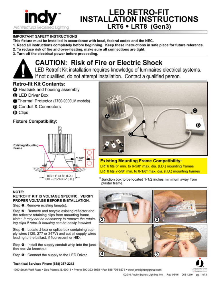
LED RETRO-FIT INSTALLATION INSTRUCTIONS LRT6 • LRT8 (Gen3) IMPORTANT SAFETY INSTRUCTIONS This fixture must be installed in accordance with local, federal codes and the NEC. 1. Read all instructions completely before beginning. Keep these instructions in safe place for future reference. 2. To reduce risk of fire and over-heating, make sure all connections are tight. 3. Turn off the electrical power before proceeding. ! CAUTION: Risk of Fire or Electric Shock LED Retrofit Kit installation requires knowledge of luminaires electrical systems. If not qualified, do not attempt installation. Contact a qualified person. Retro-fit Kit Contents: A Heatsink and housing assembly B LED Driver Box C Thermal Protector (1700-9000LM models) D Conduit & Connectors Clips E C A Fixture Compatibility: B D Existing Mounting Frame E *1.500″ min. Existing Mounting Frame Compatibility: LRT6 fits 6″ min. to 6-5/8″ max. dia. (I.D.) mounting frames LRT8 fits 7-5/8″ min. to 8-1/8″ max. dia. (I.D.) mounting frames LRT6 = 6″ to 6-⅝″ (I.D.) LRT8 = 7-⅝″ to 8-⅛″ (I.D.) *Junction box to be located 1-1/2 inches minimum away from plaster frame. NOTE: RETROFIT KIT IS VOLTAGE SPECIFIC. VERIFY PROPER VOLTAGE BEFORE INSTALLATION. Step : Remove existing lamp(s). Step : Remove and recycle existing reflector and the reflector retaining clips from mounting frame. Note: It may not be necessary to remove the retaining clips if retro-fit housing can be easily installed. 2 3 4 5 Step : Locate J-box or splice box containing supply wires (120, 277 or 347V) and cut all supply wires leading to the ballast, if fluorescent or HID. Step : Install the supply conduit whip into the junction box via knockout. Step : Connect the supply to the LED Driver. Technical Services Phone (888) 387-2212 1300 South Wolf Road • Des Plaines, IL 60018 • Phone 800-323-5068 • Fax 888-708-6578 • www.junolightinggroup.com ©2016 Acuity Brands Lighting, Inc. Rev 05/16 065-1210 pg. 1 of 3 LED RETRO-FIT INSTALLATION INSTRUCTIONS CONTINUED Step : Place LED Driver box thru ceiling cut-out and allow to rest on ceiling. Step : Its recommended that the LED Driver Box Box lies flat as shown. Top of thermal protector on LED Driver Box must be 2-3/4″ or less from top of ceiling. 6 7 8 9 10 11 12 13 14 15 Step : Pull connector whip from driver box through mounting frame. Step : Plug the new LED housing assembly connector to the connector on the end of the flex conduit provided on the driver box. Step : Push housing up through existing mounting frame. Step 11 : Insert new retaining clips (3) into slots. Step 12 : Push clips downward as you press housing firmly against the ceiling and tighten all screws. Step 13 : Verify all clips (3) are pushing down on existing fixture frame as shown. The housing may need to be rotated to avoid interference. Step 14 : Install new reflector (sold seperately). WIRING: BK WH GRN LINE COM GRN BK WH 10V OUTPUT 1-10V INPUT RTN USE WHEN DIMMING YELLOW PURPLE (+) GRAY (-) LINE COM ORG GRN ORANGE (DIMMED HOT) TO LUTRON ECOSYSTEM DIMMING BALLAST TO LED DRIVER Provided 120 or 277 VOLT LED J-BOX WIRING SUPPLY 120, 277 or 347 VOLT LED J-BOX WIRING GRN SUPPLY FROM DIMMER Step 15 : Restore power after installation of fixture is completed. PURPLE (E1 DIGITAL BUS) PURPLE/WHITE (E2 DIGITAL BUS) only on fixtures 4500 lumens and above. Technical Services Phone (888) 387-2212 1300 South Wolf Road • Des Plaines, IL 60018 • Phone 800-323-5068 • Fax 888-708-6578 • www.junolightinggroup.com ©2016 Acuity Brands Lighting, Inc. Rev 05/16 065-1210 pg. 2 of 3 0-10V DIMMABLE DRIVER 4500-9000 LUMENS DIMMABLE DRIVER DIMMABLE DRIVER DIMMABLE DRIVER DIMMABLE DRIVER 0-10V DIMMABLE DRIVER 4500-9000 LUMENS Note: Driver provides 10V output DIMMABLE DRIVER DIMMABLE DRIVER DIMMABLE DRIVER DIMMABLE DRIVER Advisory: Only one +10V out (yellow wire) used or needed to operate multiple drivers. Technical Services Phone (888) 387-2212 1300 South Wolf Road • Des Plaines, IL 60018 • Phone 800-323-5068 • Fax 888-708-6578 • www.junolightinggroup.com ©2016 Acuity Brands Lighting, Inc. Rev 05/16 065-1210 pg. 3 of 3


