Quick Reference Guide
Barrier Strips
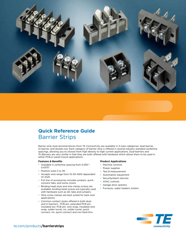
Barrier strip style terminal blocks from TE Connectivity are available in 3 main categories: dual-barrier, tri-barrier, and double row. Each category of barrier strip is offered in several industry standard centerline
spacings, allowing you to choose from high density to high current applications. Dual-barriers and Tri-Barriers are very similar in that they are both offered with hardware which allows them to be used in
either PCB or panel mount applications.
Features & Benefits
Product Applications
• Available in centerline spacing from 0.250”0.4375”
• Position sizes 2 to 30
• Accepts wire range from 10-30 AWG dependant
on style
• Full line of accessories includes jumpers, quick
connect tabs, and some covers
• Binding head style and wire clamp screws are
available; binding head screws are typically used
with hardware such as QC tabs and jumpers.
• Wire screw clamps are best suited for bare wire
applications.
• Common contact styles offered in both dual- and tri-barriers: PCB pin, extended PCB pin, insulated ext. PCB pin, wire wrap, insulated wire
wrap, solder turret, ins. solder turret, quick connect, ins. quick connect and non feed-thru
•
•
•
•
•
•
•
•
te.com/products/barrierstrips
Machine controls
Power supplies
Test & measurement
Automation equipment
Security/alarm devices
HVAC controls
Garage door openers
Furnaces, water heaters, boilers
TE Connectivity
Barrier Strips
Barrier Strip Selector Chart
Dual-Barrier
Series
3DB
Centerline
.250"
Circuits
2-30
2-30
2-16
2-16
2-30
Max Current
10A
20A
20A
20A
20A
20A
Max Voltage
300V
150V/300V
300V
300V
300V
600V
Wire Range (AWG)
16-30
14-22
12-22
12-22
12-22
12-22
Molded to Length
Molded to Length
High Rise
Molded to Length
Molded to Length
Low Rise
Molded to Length
Molded to Length
#3
#4
#4C
#6
#6C
#8
2-8
2-30
Description
4DB
4HR
JC6
NC6
.325"
SSB7
.375"
.4375"
2-27
Tri-Barrier
Series
Centerline
.250"
Circuits
2-32
.325"
2-30
.375"
.4375"
2-8
2-26
Max Current
10A
20A
15A
25A
15A
30A
Max Voltage
150-300V
150-300V
300V
300/600V
300V
600V
18-22
12-22
14-22
12-22
14-22
10-18
Molded to Length
Molded to Length
Modular
Molded to Length
Wire Range (AWG)
Description
Molded to Length
Molded to Length
Molded to Length
Double Row Barrier
1546306
1546307
1546670
1546671
Centerline
.374"
.437"
Circuits
2-30
2-26
Series
1546310
1546311
1776544
1986158
.563"
2-18
2-18
Max Current
20A
25A
30A
30A
Max Voltage
300V
300V
300V
600V
Wire Range (AWG)
Description
te.com/products/barrierstrips
12-22
14-22
10-22
10-22
Panel Mount,
Molded to Length
Panel Mount,
Molded to Length
Panel Mount,
Molded to Length
Panel Mount,
Molded to Length
TE Connectivity
Barrier Strips
Barrier Strips Overview (Types of Strips and Sockets)
Dual-Barrier
Wire Clamp Screws
Two walls or barriers are molded to each side of the terminal
screw.
The lower surface and edges of the clamping plates are
carefully designed to securely clamp the wire — with
combinations of different wire sizes — without severing
stranded wire. Extra care has been taken to produce these
components without burrs on any critical clamping surface or
edges.
Quality Plating
TE has been known for its plating, especially on the tinplated components, and has maintained stringent plating
specifications to provide a better performing, more reliable
product.
Tri-Barrier
Integral Standoffs
Three walls or barriers surround each terminal screw. The back wall safeguards field wiring. Image below:
Standoffs help rid your PCB of any remaining corrosive
agents during rinsing operations. Helps prevent trapped
solutions in the immediate PC pin area. Significantly reduces
the risk of postwave corrosion problems.
Gas-Tight Connections
The acid-tin plating on your terminals means more than just
improved shelf-life and superior solderability. It is to provide
the very basis for the heart of your wire connections.
Customization
With the large number of hardware and contact options
available, combined with various accessories, the barrier strip
line can be customized for a wide variety of solutions for your
PCB and panel mount applications.
Double Row Barriers
Used in industrial controls and machine automation. Double
row barriers are used in panel mount and wire-to-wire
applications.
Captive Clamp
(Clamping Plate)
Binding Head
vs.
The captive clamp is designed to accept multiple wires
and wire gauges. With the captive clamp, you save time!
No need to loop the wire, you just strip & screw down
underneath the clamp. The clamp rides up and down with
the screw.
te.com/products/barrierstrips
The binding head is designed to accept a single stripped
wire, looped under the screw head. The ideal use of the
binding head is in conjunction with terminated wires and
top side accessories (quick connects and jumpers).
Questions that will help you better select the product that you need:
Are you looking for a specific pin spacing?
TE offers barrier strips in both PCB and panel mount
configurations on the most common centerline spacings
ranging from 0.250"-0.4375".
Is your application for control wiring or for higher current
power connections?
For control wiring, you may desire a higher density product
such as # 3 Series Tri-Barrier or the 3DB dual-barrier. If you
need a barrier strip UL up to 600 volts, then try looking at the
SSB7 or #8 series products.
Would you like to use accessories such as flat, 45 degree or
90 degree quick connect tabs or jumper?
TE offers a wide range of accessories for each style of barrier
strip. Often times these accessories are pre-installed at our
factory for your convenience.
You may find these accessories at www.te.com/products/barrierstrips
Does your application require the block to have special
mounting features?
With the many styles of barriers available you will be able to
find flat panel mounting versions as well as vertical and right
angle through panel products.
FOR MORE INFORMATION
TE Technical Support
USA:
Canada:
Mexico:
Latin/S. America: Germany:
UK: France: Netherlands:
China: Center
+1 (800) 522-6752
+1 (905) 475-6222
+52 (0) 55-1106-0800
+54 (0) 11-4733-2200 +49 (0) 6251-133-1999
+44 (0) 800-267666
+33 (0) 1-3420-8686
+31 (0) 73-6246-999
+86 (0) 400-820-6015
Part numbers in this brochure are RoHS Compliant*, unless marked otherwise.
*as defined www.te.com/leadfree
te.com
© 2011 Tyco Electronics Corporation, a TE Connectivity Ltd. Company. All Rights Reserved.
1-1773458-2 CIS LUG FP 1M 03/2011
TE Connectivity, TE connectivity (logo) and TE (logo) are trademarks. Other logos, product and/or company names might be trademarks of their respective owners.
While TE has made every reasonable effort to ensure the accuracy of the information in this brochure, TE does not guarantee that it is
error-free, nor does TE make any other representation, warranty or guarantee that the information is accurate, correct, reliable or current.
TE reserves the right to make any adjustments to the information contained herein at any time without notice. TE expressly disclaims all
implied warranties regarding the information contained herein, including, but not limited to, any implied warranties of merchantability or
fitness for a particular purpose. The dimensions in this catalog are for reference purposes only and are subject to change without notice.
Specifications are subject to change without notice. Consult TE for the latest dimensions and design specifications.


