Goal of this chapter is to learn how the magnetic inductance
advertisement

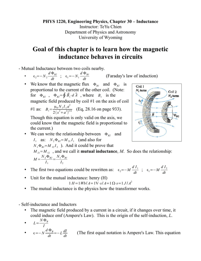
PHYS 1220, Engineering Physics, Chapter 30 – Inductance Instructor: TeYu Chien Department of Physics and Astronomy University of Wyoming Goal of this chapter is to learn how the magnetic inductance behaves in circuits - Mutual Inductance between two coils nearby. • ϵ 2=−N 2 d Φ B2 ; dt ϵ1 =−N 1 d Φ B1 dt (Faraday's law of induction) • We know that the magnetic flux Φ B1 and Φ B2 is proportional to the current of the other coil. (Note: for Φ B2 , Φ B2=∮ B⃗1⋅d ⃗A , where B1 is the magnetic field produced by coil #1 on the axis of coil #1 as: B1= μ 0 N 1 I 1 a2 2 (x 2+a 2)3 /2 (Eq, 28.16 on page 933). Though this equation is only valid on the axis, we could know that the magnetic field is proportional to the current.) • We can write the relationship between Φ B2 and I 1 as: N 2 Φ B2=M 21 I 1 (and also for N 1 Φ B1=M 12 I 2 ). And it could be prove that M 21=M 12 , and we call it mutual inductance, M. So does the relationship: M= N 2 Φ B2 N 1 Φ B1 = I1 I2 d I1 ; dt • The first two equations could be rewritten as: ϵ2=−M ϵ1 =−M d I2 dt • Unit for the mutual inductance: henry (H) 1 H =1Wb / A=1V⋅s / A=1 Ω⋅s=1 J / A 2 • The mutual inductance is the physics how the transformer works. - Self-inductance and Inductors • The magnetic field produced by a current in a circuit, if it changes over time, it could induce emf (Ampere's Law). This is the origin of the self-induction, L. • • N ΦB I d ΦB dI ϵ=−N =−L dt dt L= (The first equal notation is Ampere's Law. This equation describes the self induced emf) • In other words, when the current-carrying wire is bended into coil shape and placed in a circuit, the time-dependent current will produce a self-induced emf and affect the circuit behavior. • The notation used for inductor in circuit is: dI • This self-induced emf in circuit is described as: Δ V =L dt You Do Example 30.3 on page 997. I Do Exercise 30.15 (a) on page 1014. - Magnetic field energy stored in inductor dU di =P=Vi= Li • dt dt I • dU = Li di ; so 1 2 U =∫ Li di = LI 2 0 2 • energy density (energy per volume) stored in magnetic field: u= U = B V 2 μ0 - Circuits: (R-L circuit, L-C circuit, and R-L-C circuit) • R-L circuit • I ( t)= ϵ (1−e−(R / L)t ) (When S1 closed R while S2 opened). Current increases and saturates . • I ( t)=I 0 e−(R / L)t (When S2 closed while opened) Current decays exponentially. L • Time constant: τ= R S1 • • • L-C circuit q (t)=Q cos (ω t+ϕ) I ( t)=−ω Q sin(ω t+ϕ) • oscillation frequency, f, and phase frequency, ω : ω=2 π f = √ 1 LC • The current and charge are oscillating back and forth between capacitor and inductor. The energy is transferred back and forth between electric field (in capacitor) and magnetic field (in inductor). • R-L-C circuit • We know that the resistor, R, is the damping source (consume the energy); while capacitor and inductor store energy in them. When combine these three together, you should expect to see the oscillation of current and charge between capacitor and inductor with damping through the resistor. • q (t)= A e−(R /2L )t cos( √ 1 R2 − 2 t+ϕ) LC 4L • oscillation phase frequency in R-L-C circuit: ω ' = √ 1 R2 − 2 LC 4L Math Preview for Chapter 31: • Trigonometric functions • Oscillation as functions of time Questions to think about for Chapter 31: • We only discussed the circuits with dc voltage (current). And we know that the induction depends on the change of current as function of time. What if the ac voltage (sin function) is applied to the circuit. How will the circuit react?


