MEASURING INDUCTANCES ON A DC MACHINE

MEASURING INDUCTANCES ON A DC MACHINE
Ning Chuang, Timothy Gale, Richard Langman
School of Engineering, University of Tasmania
GPO Box 252-65, Hobart, Tasmania 7001 Australia
E-mail: T.Gale@utas.edu.au
ABSTRACT
This paper des cribes a new method of measu ring selfinductance and mutual i nductance on a DC machine. The method used a DC source and overcame some problems associated with t raditional methods usi ng an AC source. In pariticular, it enabled the field win ding to carry rated DC.
The new method demon strated the feasibility of taking measurements of inductance values on a DC machine, and current which gave magnetic saturation close to the flux on the actual machine while running. Methods for measurin g both self and mutual inductance of DC machine armat ure coils were developed.
L
1
=
1
+
R
1
/R
2
I
1
1
V =
1
+
R
1
/R
2
∞
∫
0
Vdt
L
1 di
1 dt
(1)
Derivation of Equation (1)
The steady state of the bridge is reached after the switch has been closed and R
2
, R
3
and R
4
are adjusted until V = 0.
Their steady state values are then given by R
1
/R
2
= R
3
/R
4
.
Open the switch, then
(2)
KEY WORDS
DC machine, magnetic saturation, inductance.
1. Introduction
Due to the required data of t he inductance values for the
DC machine model, it was necessary for us to take the measurement of self and mutual inductances on t he real machine. Traditi onally, an AC method would be used for measuring inductance which needs to measure the current and voltage, and calculate the impedance finding both real and imaginary parts.
However, this AC method did not wo rk on the DC machine, because the measured values can be varying with different frequencies.
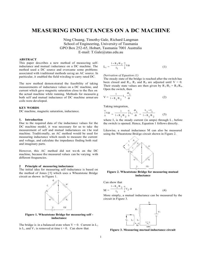
2 Principle of measuring inductance
The initial idea for measuring self -inductance is based on the method of Jones [ 5] which uses a Wheatstone Bridge circuit as shown in Figure 1.
R
1
L
1
I
1
V
R
2
R
3
R
4
V
1
SW
Figure 1. Wheatstone Bridge for measuring self inductance
The bridge is in a balanced st ate when V = 0. Current in L
1 is I
1
, and V
1
is removed at time t = 0. Can show that
Taking integration,
∞
∫
0
Vdt
1
=
1
+
R
1
/R
2
∞
∫
0
L
1 di
1 dt
=
L
1
×
I
1
1
+
R
1
/R
2
(3) where I
1 is the steady current (in amps) through L
1 before the switch is opened. Hence, Equation 1 follows directly.
Likewise, a mutual inductance M can also be measured using the Wheatstone Brid ge circuit shown in Figure 2.
V
2
L
2
M
I
1
L
1
R
5
R
3
R
1
V
1
V
R
4
SW
1
R 2
Figure 2. Wheatstone Bridge for measuring mutual inductance
Can show that
1
+
R
1
/R
2
M =
I
1
∞
∫
0
V
2 dt
(4)
More simply, a mutual inductance can be measured by the circuit in Figure 3.
R
1
1
V
1
V
2
L
2
L
1 t =
0
M
SW
1
Figure 3. Measuring mu tual inductance circuit
1
Thus,
M =
1
I
1
∞
∫
V
2
0 dt
(5)
In practice, errors due to resi dual flux are avoided by reversing I
1
during the integrating period, and then
M =
2
×
1
I
1
∞
∫
0
V
2 dt
(6)
The actual measurement on the DC machine used a D irect
Current Inductance Bridge (DCIB) in the Power Laboratory of the School of Engineering. This DCIB unit consists of three main parts: a Kelvin Double Bridge (instead of a
Wheatstone Bridge), an electronic in tegrator (INT), and a digital voltmeter (DVM) , as in Figure 4.
L
1
V
1
R
3
SW
R
4
R
2
R
1
C
R
3
R
4
R
INT
R
DVM
Figure 4. Direct Current Inductance Bridge
(A Kelvin Double Bridge is a development of the
Wheastone Bridge to eliminate the errors due to the contact and lead resistance, and is suitable for t he measurement of low resistances.)
3 Armature inductance measurements
3.1 Connection of the armature into the DCIB
To establish t he equivalent circuits on the DC machine [6], the DCIB circuit needed to be modified for each measurement. To measure the self -inductance of the six sub-coils in series for the 7-coil circuit, the connection to the DCIB was as in Figure 5.
4C
5C
6C 7C
8C
I=2A
A
3C
2C Davey
9C
10C
R
2
Ratio
V
1
1C 11C V
0
∞
16C
15C
14C
13C
12C
SW
1
I=2A
R
3 R
4
Figure 5. Measuring self -inductance for the 7 -coil circuit
It can be seen that the segments from 1C to 3C and from 9C to 11C are s horted out and ideally carry zero current. The series connected coils 9C - 3C and 11C - 1C have 1 amp flowing throu gh them from the supply V
1
. The DCIB measures the self -inductance of two sets of the six sub -coils in parallel. In this di agram, the field circuit is not shown, but it carries 0.2A DC during the measurement.
2
3.2 Effect of magnetic saturation on measured inductances
The 0.2A field current was set for the saturated field flux, which produces approximately the same amount of flux as
5A in the complete armature.
Rated field current I f
is 0.2A, and reated armarture current
I a
is 3.2A. In order to select values of I a
for the sub-coil inductance measurements, we examined whether the inductance depended on armature current.
This was done by using the DCIB and a 20 -turn coil that was temporarily wound around one pole of the machine.
The inductance was measured with 0.2A in the field coil.
We found that t he different armature currents from 1A to
3A did not vary the inductance signifi cantly (ie. only a few percent difference), which was close to the inherent error in this method. A sub -coil inductance was then measured under a similar flux condition to what would exist when the motor is running.
It was also found by mutual inductance measurement that the 0.2A field current produced the sam e amount of flux as
5A armature current, when the rotor was turned, so that the armarture flux.
Under the unsaturated condition (ie. a zero field current) the self-inductance of the total armature winding varies with angular position. Referring to Figure 6, the self-inductance measured between the segments 2 and 10 was fo und to vary almost sinusoidally between 0.15H and 0.31H as the rotor was turned. By contrast, when there was 0.2A field current, the armature self -inductance was 0.07
±
0.01H, almost independent of the rotor position. Thus, the self and mutual inductances of the armature sub -coils can be assumed to be constant and i ndependent of the armature current used and their location on the rotor.
3.3 Measuring other self -inductance on the machine
We also needed to measure other coils of less than six armature coils i n series of the machine for the faulty machine model. The concept of measuring self -inductance remains the same. The only modification is to add a piece of wire into the armature, which will short some coils depending on how many coils of self-inductance are needed to be measured. For example, Figure 6, is the connection to measure a two coil self -inductance in the 7 -coil circuit of the DC machine’s armature (coil numbers from 7C to 3C and from 13C to 1C in Figure 6).
3C
2C
4C
5C
6C 7C
Davey
I=2A
8C
9C
10C
I=2A
A
R
2
Ratio
V
1
1C
16C
15C
14C
13C
12C
11C
R
3
V
0
∞
R
4
SW
1
Figure 6. Measuring self -inductance on different coils for the 7-coil circuit
Hence, one to five coil self -inductance for the 7 -coil circuit can be measured in the same way. To measure selfinductance in the 5 -coil equivalent circuit, the changes made in this connecti on were to short one coil at both ends
(10C-9C and 2C-1C in Figure 7), as required by the commutating condition.
2C
1C
3C
4C
5C 6C
Davey
I=2A
7C
8C
9C
10C
A
R
2
Ratio
16C
15C
14C
13C
12C
11C
V
0
∞
SW
1
R
3 R
4
Figure 7. Measuring self -inductance on different coils for the 5-coil circuit
3.4 Measuring mutual inductance on the machine
The new method used for measuring mutu al inductance for the 7-coil equivalent circuit is in Figure 8.
To integrator
V
0
∞
3C
4C
5C 6C
7C
8C
I=2A
2C
1C
I=2A
9C
Davey
10C
A
V
1
16C
15C
14C
13C
12C
11C
SW
1
Figure 8. Measuring mutual inductance on different coils for the 7-coil circuit
In Figure 9, the integrate d voltage V
0
∞
on three coils from
3C to 6C is attr ibuted to the current flowing through from
9C to 6C. Thus, it is considered that the mutual inductance is produced between these two circuits.
It is noted that there is a 1.6
Ω
rheostat connected between
6C and 3C as shown in Figure 9. This was because of the small voltage (ie. only a few millivolts) between 6C and
3C. This adversly affected the total voltage of the integrator. This probl em was solved by adjusting the sli de position until t here was less than 1mV cross 3C-6C before the current was reversed. Similarly, each different mutual inductance on the machi ne was measured based on this method.
4 Production of mutual i nductance and verification with the measurements
It is necessary to verify the measurements we obtained.
Each segment was 22.5
°
apart on the armature for this 2 pole/16 slot machine. Hence the mutual inductance M
31 defined between 9C-6C and 5C-6C can be written as M
×
cos 22.5
°
31Max
with the current directio n from 9C to 6C. Also
M
31
M
of 9C-6C with 4C-5C and 3C- 4C can be given as
31Max
×
cos 45
°
and M
31Max
×
cos67.5
°
etc.
Refering to Figure 9, the measured results of the mutual inductance on t he DC Machine with I = 2A can be summarised in Table1.
Connected
Coils
Measured V
(Volt)
0
∞
M =
2
1
+
×
I
Ratio
×
Rate
(mH)
V
0
∞
Notation of
MI
3C - 4C 0.10 2.6 M
31
3C - 5C 0.29 7.2 M
32
3C - 6C
4C - 5C
4C - 6C
5C - 6C
0.57
0.20
0.48
0.28
14.0
5.0
12.0
7.0
M
33
M
31
M
32
M
31
Table 1. Three coil mutual inductance in the 7 -coil circuit
In the above tabl e, each mutual inductance is denoted with a last number s ubscript for a number o f coils affected by the flux linkage of the current thr ough from 9C to 6C. It will be noticed that th e measured mutual inductances of M
31 or M
32 in the different coil positions are obviously different.
The single coil, for exampl e, between 3C and 4C, 4C and
5C or 5C and 6C is m agnetically coupled by a different flu x linkage depending on the angle
θ
. Therefore, the flux linkage associated mutual inductance to each single coil is given to cos
θ
, as presented in Figure 9.
N
ω
Davey S d -axis
Figure 9. Rotating position
θ
dfinition
Theoretically, these mutual inductances should be expected including the term of cos
θ
as:
M
31Max
× cos 22.5
o
0 .
924
M
31Max
× cos 45 o =
0 .
707
= 1.31
M
31Max
× cos 45 o
0 .
707
M
31Max
× cos mH, and M
31
67.5
o =
0 .
383
The measured value of M
= 1.85
31
for 5C - 6C at 22.5
for 4C - 5C at 45
°
was 7.0
°
was 5.0 mH. Thus we have
7.0/5.0 = 1.4. This answer is close to the value of 1.31 from the calculation. Thus, an error obtai ned for this is (1.4-
1.31)/1.31 = 0.069, or 6.9 %.
3
If we substit ute the measured value 2.625 to M
4C at 67.5
°
31
on 3C -
, then 5.0/2.6 = 1.92 is obt ained. It can be considered that the measurement is also close to the calculated
M
31Max
M
31Max
× cos 45 o
× cos 67.5
o
which is 1.85, and the absolute error involved here is 1.92 -1.85 = 0.07. The error is given as (1.92 – 1.85)/1.85 = 0.04, or 4 %.
This is another way to explain these angles. So the given angles in the calculations about the mutual inductances on the armature winding can be verified, and are found to exist in intervals of 22.5
°
, such as 22.5
°
, 45
°
, 67.5
°
and 90
°
etc.
Figure 4.14 is just a particular case if the mutual inductance between a 3-coil inductance (8C -6C) and 1-coil inductance
3C, shown as an exa mple of the 90
°
angular between them.
Figure 10 illustrates the flux directions of 8C -6C and 3C which forms a 90
°
angle.
Φ
3C
1C
2C
16C
3C
4C
Φ
6C-8C
5C
90°
6C
7C
8C
9C
15C 10C
14C 11C
13C 12C
Figure 10. A mutual inductance angle with the flux directions
5 Impact of the measured inductance values in the model
In our measurement of the armature current I a
[6], the peakto-peak ripple is about 10.5 %. However, the ripple of t he simulated I a
is about 8.5 %. The ripple percentage in the model should be affected by the inductances of the armature winding.
We checked whether the model’s output I a
ripple current can be changed by varing its inductance values. We first doubled every self-inductance and mutual inductance.
Figure 11 shows the ripple of the simulated I a
.
Figure 11. Simulated I a
with doubled inductances
The I a
ripple becomes smaller, reducing to about 4 % peak to-peak ripple. We then halved all self and mutual inductance's, and the ripple increased as in Figure 12.
Figure 12. Simulated I a
with halved inductances
Thus, there is an inverse relationship between the inductance values and the ripple amplitude in the current I a
.
In other words, doubli ng inductances led to a 50% reduction in I a
, and halving the inductances l ed to a 100% increased in I a
. The evidence indicates that the inductances obtained from the measurements might be too high.
6 Conclusion
This new method of measuring self and mutual induct ance using a DC source has been demonstrated. However, the existence of this method was not perfect. For accurate modelling results, the inductances must be measured under conditions approximating as closely as possible to those of normal operations.
7 Acknowledgements
The authors would like to acknowledge the assistance of Mr
Steve Avery and Mr Gl enn Mayhew in providing technical assistance relating to the experimental work.
8 References:
[1] S.Y.S. Ho, Condition monitoring of electric motors .
PhD thesis, University of Tasmania, Australia, 1999.
[2] S.Y.S. Ho and R. Langman, The mathematical model of a DC motor, Proc. AUPEC’98, University of Tasmania,
Australia, Sept 1998, 2 , 389-394.
[3] A.G. Innes, Condition monitoring of induction motors: the detection of broken rotor bars in variable speed induction motor drivers, PhD thesis, University of
Tasmania, Australia, 1996.
[4] S.Y.S. Ho, and R. Langman, Stator current frequency analysis for the condition monit oring of induction motors,
J. Electrical and Electronics Eng., Australia, 17 (1), 43-70,
March 1997.
4
[5] C.V. Jones, The unified theory of electrical machines ,
Butterworths, Londo n, 1967.
[6] N.Chuang, T.Gale and R.Langman, Model based simulation on a DC machine , AUPEC, Hobart Australia,
2005.
5


