Get Precision Performance from a Digitally
Controlled Potentiometer (DCP)
®
Application Note
June 5, 2009
Typical resistance accuracy of the polysilicon DCP is in
±20% range. However, the relative accuracy or matching of
the resistive elements in the particular resistor array is
excellent, and usually is in range of ±1% or better. Thus, this
discrepancy between relative and total accuracy should be
carefully calculated during the design stage in order to avoid
or minimize an additional adjustment of the application
circuitry in production. In this application note we will discuss
how the DCP accuracy affects the design and some
techniques to improve final system accuracy.
VIN
AN1425.1
VCC
U1
RH
RTOTAL
±20%
V+
INRW
RL
OUT
VOUT
±1%
IN+
V-
There are two major uses of DCP in application design – as
a voltage divider and as a variable resistor.
Voltage Divider Mode
GND
GND
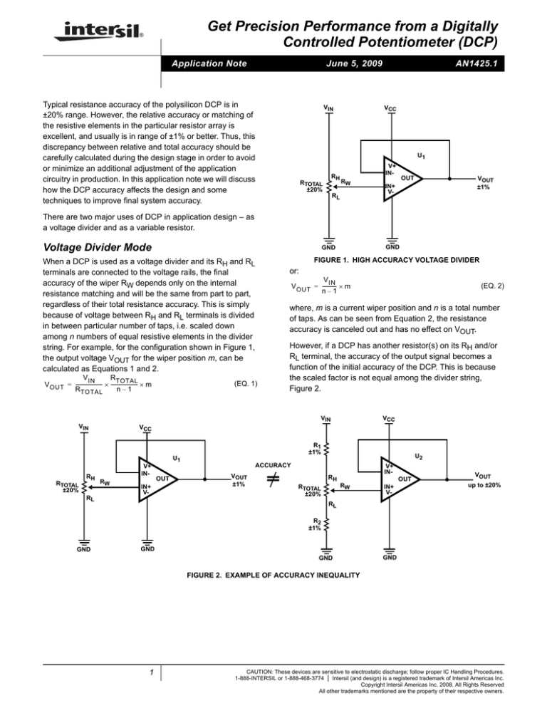
FIGURE 1. HIGH ACCURACY VOLTAGE DIVIDER
When a DCP is used as a voltage divider and its RH and RL
terminals are connected to the voltage rails, the final
accuracy of the wiper RW depends only on the internal
resistance matching and will be the same from part to part,
regardless of their total resistance accuracy. This is simply
because of voltage between RH and RL terminals is divided
in between particular number of taps, i.e. scaled down
among n numbers of equal resistive elements in the divider
string. For example, for the configuration shown in Figure 1,
the output voltage VOUT for the wiper position m, can be
calculated as Equations 1 and 2.
R TOTAL
V IN
V OUT = ----------------------- × ----------------------- × m
R TOTAL
n–1
or:
V IN
V OUT = ------------ × m
n–1
where, m is a current wiper position and n is a total number
of taps. As can be seen from Equation 2, the resistance
accuracy is canceled out and has no effect on VOUT.
However, if a DCP has another resistor(s) on its RH and/or
RL terminal, the accuracy of the output signal becomes a
function of the initial accuracy of the DCP. This is because
the scaled factor is not equal among the divider string,
Figure 2.
(EQ. 1)
VCC
VIN
VIN
(EQ. 2)
VCC
R1
±1%
U1
RTOTAL
±20%
RH
RL
V+
INRW
IN+
V-
OUT
U2
ACCURACY
VOUT
±1%
=
V+
IN-
RH
OUT
RW
RTOTAL
±20%
IN+
V-
VOUT
up to ±20%
RL
R2
±1%
GND
GND
GND
GND
FIGURE 2. EXAMPLE OF ACCURACY INEQUALITY
1
CAUTION: These devices are sensitive to electrostatic discharge; follow proper IC Handling Procedures.
1-888-INTERSIL or 1-888-468-3774 | Intersil (and design) is a registered trademark of Intersil Americas Inc.
Copyright Intersil Americas Inc. 2008. All Rights Reserved
All other trademarks mentioned are the property of their respective owners.
Application Note 1425
The output function for the circuitry with R1 and R2 in
Figure 2 is as shown in Equation 3:
V IN
R TOTAL
V OUT = -------------------------------------------------- × ⎛ R 2 + ----------------------- × m⎞
⎝
⎠
R 1 + R TOTAL + R 2
(n – 1)
(EQ. 3)
improved by using certain techniques. For example, the
design in Figure 2 can be slightly modified in order to get
higher accuracy, as shown in Figure 4.
where n is the total number of taps and m is the current
wiper position.
Note that wiper resistance is not included, because it has no
effect in this particular configuration, assuming that we have
an ideal Op Amp.
R1
±1%
R2
±1%
U2
RTOTAL
±20%
V+
IN-
RH
RW
VOUT
±2%
OUT
IN+
V-
RL
Rheostat Mode
When a DCP is used as a variable resistor, its output
accuracy becomes a combination of initial accuracy (± 20%)
plus an additional error from wiper resistance, since the
wiper switch is not ideal (it has a small resistance, typically
about 70Ω) and its value may vary among the taps. The
wiper resistance can be lowered in rheostat configuration,
e.g. when the wiper is connected to one of the end terminals
(see Figure 3A).
RH
RW
RTOTAL
±20%
RH
RL
RW
RTOTAL
±20%
VCC
VIN
R3
±1%
GND
GND
FIGURE 4. EXAMPLE OF INCREASED ACCURACY IN
VOLTAGE DIVIDER MODE
In Figure 4, the input signal VIN is divided by the string of
fixed resistors R1, R2 and R3, and a DCP is placed in
parallel with R2. This configuration preserves the flexibility of
the variable output with much higher accuracy. Note that in
order to get desired accuracy, the value of RTOTAL has to be
about five to ten times the value of R2.
Better accuracy comes when the DCP is used as a variable
resistor by combining the DCP with high precision fixed
resistors in parallel and serial configuration, Figure 5.
RL
GND
R1
±1%
GND
FIGURE 3A.
FIGURE 3B.
FIGURE 3. RHEOSTAT/VARIABLE RESISTOR CONFIGURATION
In rheostat configuration (Figure 3A), wiper resistance
appears in parallel with the part of the resistor string and its
effect depends on the selected wiper position.
Another possible configuration is to leave one of the end
terminals floating as in Figure 3B. In this case, the wiper
resistance is well known and usually provided as a graph in
a data sheet that makes calculation of total resistance at
each tap much easier. Equation 3 can be used to calculate
resistance at tap m
R TOTAL
R m = ----------------------- × m + R WIPER + R OFFSET
n–1
RTOTAL
±20%
RH
RW
R2
±1%
RL
FIGURE 5. DCP IN BOTH SERIAL AND PARALLEL
CONFIGURATION WITH FIXED RESISTORS
For example, using ±20% 10k 256 taps DCP and circuitry as
in Figure 5, we can get a variable resistor from 5.5k to
10.695k with accuracy distributed from ±1.1% to ±8.5%,
(Table 1).
(EQ. 4)
Design Examples Allow Increases in
Circuitry Accuracy
Even though the initial accuracy of the regular DCP is in
±20% range, the accuracy of the application can be
2
AN1425.1
June 5, 2009
Application Note 1425
TABLE 1. DCP IN BOTH SERIAL AND PARALLEL CONFIGURATION WITH FIXED RESISTORS
DCP Rtotal
(kΩ)
R1
(kΩ)
R2
(kΩ)
MINIMUM
TOTAL
RESISTANCE,
DCP AT TAP 1
(kΩ)
Min
8
6.742
29.106
5.495
9.786
0.021
Nom
10
6.81
29.4
5.555
10.695
0.026
Max
12
6.878
29.694
5.615
11.541
0.031
There is also the ISL22317, a 1% precision, non-volatile,
128 tap DCP available with the resistance options of 10k,
50k and 100k that can be configured either as a two-terminal
variable resistor or as a three-terminal potentiometer. The
ISL22317 provides high accuracy, 0Ω of wiper resistance
and low temperature coefficient, eliminating the need for
complex precision algorithms and other additions.
MAXIMUM TOTAL
RESISTANCE,
DCP AT TAP 255
(kΩ)
STEP
RESOLUTION
(kΩ)
TOTAL
ACCURACY
FOR TAP 1
TOTAL
ACCURACY
FOR TAP 255
-1.08%
-8.50%
1.08%
7.90%
within limited range, an 8-bit DCP can achieve even better
resolution than a 10-bit DAC. The DCP resolution table as a
function of terminal voltages and number of taps is shown in
Table 2.
Another practical usage of the DCPs is an alternative to the
DACs. In most cases when the design needs fine tuning
TABLE 2. DCP RESOLUTION PER TAP
DIFFERENTIAL
TERMINAL
VOLTAGES: VH-VL
16 Taps
32 Taps
64 Taps
100 Taps
128 Taps
256 Taps
1024 Taps
4 Bits
5 Bits
6 Bits
7 Bits
7 Bits
8 Bits
10 Bits
10V
667
323
159
101
79
39
10
9V
600
290
143
91
71
35
9
8V
533
258
127
81
63
31
8
7V
467
226
111
71
55
27
7
6V
400
194
95
61
47
24
6
5.5V
367
177
87
56
43
22
5
5V
333
161
79
51
39
20
5
4V
267
129
63
40
31
16
4
3V
200
97
48
30
24
12
2.9
2V
133
65
32
20
16
8
2.0
1V
67
32
16
10
8
3.9
1.0
0.5V
33
16
8
5
3.9
2.0
0.5
NOTE: Resolution (chart specifies LSB in mV/tap)
Intersil Corporation reserves the right to make changes in circuit design, software and/or specifications at any time without notice. Accordingly, the reader is cautioned to
verify that the Application Note or Technical Brief is current before proceeding.
For information regarding Intersil Corporation and its products, see www.intersil.com
3
AN1425.1
June 5, 2009


