971 KB
advertisement

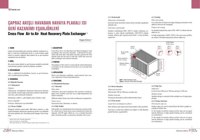
Teknik not ÇAPRAZ AKIŞLI HAVADAN HAVAYA PLAKALI ISI GERİ KAZANIMI EŞANJÖRLERİ Cross Flow Air to Air Heat Recovery Plate Exchanger 1 4.1.3 Sızdırmazlık 4.1.3 Sealing Plaka kenar sızdırmazlığı Plate side sealing Çok katlı kenar kenetleme (bazen kenet arasında yapışkanlı) şeklinde olur. It is in the form of multi-level edge clamping (sometimes with adhesive between the clamping). Ürün kenar sızdırmazlığı Product side sealing Standart sıcaklıklarda (900 -100°C’a kadar) silikonsuz yapıştırıcı vs. gibi; yüksek sıcaklıklarda (200-250°C) yüksek sıcaklık silikonu gibi yapıştırıcılarla finler ve köşe profiller yapıştırılır. In standard temperatures (up to 90ºC-100º C) without silicone adhesive etc. In high temperatures (200ºC-250ºC), fins and corner profiles are sealed with high-temperature silicone adhesives. Hagop Kartun 2 Profil Tipleri Profile Types 1. DESCRIPTION Çapraz akış prensibine göre çalışırlar, plakalar yardımıyla soğuk ve sıcak hava birbirinden ayrılır ve sıcak taraftan soğuk tarafa ısı transferi sağlarlar. Bazı plakalı tip ısı geri kazanım eşanjörleri nem de iletirler. Cross Flow Air to Air Heat Recovery Plate Exchangers work according to the cross flow principle. Cold and hot air separated with each other with plates and they generate the heat transfer from the hot side to cold side. Some heat recovery plate exchangers also transmit moisture. 2. AMAÇ Bu yazının amacı plakalı ısı geri kazanım eşanjörü seçiminde tasarımcılara yardımcı olacak ön bilgileri vermektir. 3. UYGULAMALAR Oda ve endüstriyel havalandırma, kış/yaz ısı geri kazanımı, taze ve atılan havanın ayrılması 4. TASARIMSAL 4.1 Mekanik Tasarım 4.1.1 Malzemeler The purpose of this article is to provide the initial information to designers in the selection of cross flow air to air plate heat exchangers. Tip-2 Type-2 Tip-2 Type-2 Kenar profili Profile Kenar yapıştırıcı Corner sealing Plakalar (finler) Plate (fins) Pla Fin kalı ned (fin len li) b gh oy mm mm 3. APPLICATIONS Room and industrial ventilation, winter/summer heat recovery, separation of fresh and exhausted air. 4. STRUCTUREL Tip-1 Type-1 Kapak Cover Şekil 1. Plakalı Eşanjörün Yapısı Figure 1. Structure of Plate Heat Exchanger 4.1 Mechanical Structure 4.1.4 Edge Size 4.1.1 Materials 4.1.4 Kenar Boyutları Alüminyum, ön-kaplamalı alüminyum (korozyona dayanım için); plastik; reçineli kağıt; paslanmaz (yüksek sıcaklık kullanımı için) gibi malzemeler kullanılır. Plates (fins) Aluminum, pre-coated aluminum (for corrosion resistance), paper resin, stainless steel (for use in high-temperature) are used as materials. Tekparçalı dizaynlar Kabartmalı, ondüle vs. gibi değişik yüzey formları vardır. Different surface forms exist such as embossed, corrugated etc. Tek parçalı dizaynların çoklu kullanımından oluşur. Moduler design Modular design is consisted of the multiple use of single-piece designs. Çerçeve kapaklar 4.1.5 Ürün Seçimi 4.1.5 Product Selection Galvaniz, alüminyum veya aluzinkdir. Frame covers Galvanized steel, aluminum, or aluzinc. Uygun kenar uzunluğunun seçilmesi Choosing the edge size 4.1.2 Kenar Profiller 4.1.2 Side Profiles Hava debisine göre ürün kenar boyutu Şekil 2’den seçilebilir. Köşegeni azaltma amaçlı pahlı, 900 köşeli, çıkıntılı vs. gibi çeşitli formlarda alüminyum ekstrüzyon profil veya bükümlü alu levha şeklinde olur. Genellikle profil kapağa vida ile bağlanır. Side profiles are manufactured from aluminum extrusion profiles, which exist in various forms such as chamfered to reduce the diagonal, with 90º angle, ribbed etc. or as a bended aluminum plate. Generally, profile is connected to side plate with a screw. Taze hava ve atılan hava debileri eşit değilse ve fark büyükse paralel besleme uygulanabilir. Product edge size can be selected from the below graphic according to airflow rate. Plakalar 1 İngilizce metin yazarı tarafından sağlanmıştır. Karyer Isı Transfer AŞ., Teknik Müdür Karyer Heat Transfer Inc., Technical Manager, İstanbul, Turkey, hkartun@karyer.com 2 Cilt: 54 Sayı: 646 2. PURPOSE Kapak Cover Kenar uzunluğu mm Side length mm 1. TANIM 60 Mühendis ve Makina 200 mm’den 700 ila 1200 mm’ye kadar olur. Modüler dizaynlar Single part It can be from 200 mm to 700 mm and up to 1200 mm. If the outside air and the exhaust air flow rates are not equal and the difference is high, paralel feeding can be considered as an alternative. If the outside air and the exhaust air flow rates are not equal and the difference is high, paralel feeding can be considered as an alternative. Mühendis ve Makina 54 61 Cilt: Sayı: 646 Basınç Kaybı/Pressure Drop (Pa) Boyut Size (mm) Debi Flow Rate (m3/h) Şekil 2. Hava Debisine Uygun Kenar Uzunluğu Seçimi Figure 2. Edge Size vs Air Flow 4.1.6 Basınç Kaybı 4.1.6 Pressure Drop Ekonomik nedenlerden dolayı eşanjör içi basınç kaybı 150 ila 250 Pa arasında alınır. Plakalar arası mesafe (hatve) küçük ürünlerde 2 ila 6 mm arası, büyüklerde 4 ila 12 mm arası değişir. For economical reasons, the pressure loss in heat exchangers is assumed as between 150 and 250 Pa. The distance between the plates (fin spacing) is between 2 and 6 mm for small products and it is between 4 and 6mm for bigger products. Sıcak Hot Soğuk Köşe Cold Corner 4.1.8 Eşanjör Uzunluğu Kenar uzunluğu ve hızı belirlenen eşanjörün uzunluğu da belirlenmiş demektir. Maksimum eşanjör uzunluğu, kenar uzunluğuna bağlı olarak üreticiler tarafından belirlenir. Soğuk Cold Şekil 3. Paralel Besleme Figure 3. Paralel Feeding Verim/Effidency (%) Eşanjör alın hızı kabul edilir basınç kaybı seviyesine göre seçilir. Genelikle üreticiler alın hızını verirler. Plakalar içi kanal hızı alın hızının yaklaşık 2 katıdır. Soğuk Cold 4.1.7 Hız Cilt: 54 Sayı: 646 62 Mühendis ve Makina Frontal velocity of the heat exchanger is selected according to the accepted pressure loss level. In general, manufacturers use the frontal velocity. Channel velocity in plate is approximately two times of frontal velocity. 4.1.8 Exchanger Length If the edge length and velocity of the heat exchanger is determined, it means that the length is also defined. Maximum length of the heat exchanger is determined by manufacturers depending on the length of the edge. Verim, basınç kaybı ve kapasitenin farklı hızlarda ve değişik ürünlerdeki eğrileri aşağıda verilmiştir. Eğrilerde sırasıyla ürün kenar kenar uzunluğu (cm), eşanjör uzunluğu (cm), hatve (mm) ve atılan hava kütlesel debisinin taze hava kütlesel debisine oranı (1 den farklı ise) ürün tanımında belirtilmiştir. 4.1.7 Velocity Sekil 4. Verim Figure 4. Efficiency Alın Hızı/Frontal Velocity (m/s) Efficiency, pressure drop and capacity curves at different velocities and different products are given below. Product edge length (cm), heat exchanger length (cm), fin spacing (mm) and the mass flow rate of exhaust air to the mass flow rate of fresh air (if different than 1) Alın Hızı/Frontal Velocity (m/s) Şekil 5. Basınç Kaybı Figure 5. Pressure Drop Hız azalınca, hatve azalınca, boyut büyüdüğünde, kütle oranı artınca verim artmaktadır. Hız artınca, hatve azalınca, ürün büyüdüğünde, kütle oranı arttığında kapasite artmaktadır. 4.1.9 Verim Isıtmada verim % 50-65 civarında olur. Malzemenin cinsinin ve kalınlığının verimliliğe etkisi azdır. Bu nedenle çok farklı malzemelerde plakalı eşanjör üretilmektedir. Yüzey formunun etkisi önemlidir. Seri bağlı birden fazla plakalı eşanjörün toplam verimi üretici softwareleri ile hesaplanabilir. Eşanjör içinde sıcak hava tarafında yoğuşma olması, kazanılan gizli ısı nedeniyle eşanjörün kışın veriminin artmasına neden olur. Kuru verim (yoğuşma yoksa) şu şekilde hesaplanır: E2= m2(t22-t21)/ (mmin (t11-t21) E: Verim m2: soğuk taraf kütlesel debisi kg/h mmin: kütlesel debisi az olan tarafın debisi kg/h t: sıcaklık oC 1: sıcak hava 2: soğuk hava are shown in curves respectively and indicated in product definition. Efficiency increases, when the velocity decreases, the fin spacing decreases, the size enlarges and the mass ratio increases. Pressure drop increases, when the velocity increases, fin spacing decreases and the product enlarges. Capacity increases, when the velocity increases, product enlarges, fin spacing decreases and the mass ratio enlarges. 4.1.9 Efficiency or Effectiveness In heating, efficiency is approximately 50–65%. Material type and thickness has a minor effect on efficiency; for this reason, plate heat exchangers are manufactured from many different materials. Surface form has significant effect in efficiency. Plate heat exchangers multiple connected in series total efficiency are calculated with producer softwares . Condensation in the hot air side of the heat exchanger creates a hidden heat and consequently efficiency increases at winter. Dry efficiency (in case of no condensation) is calculated as follows: E2= m2(t22-t21)/ (mmin (t11-t21) E: Efficiency m2: cold side mass flow rate kg / h mmin: flow rate of the side with less mass flow rate kg/h t: temperature oC 1:hot air 2:cold weather Mühendis ve Makina 54 63 Cilt: Sayı: 646 Kapasite/Capacity (kW) 4.2 Diğer Özellikler 4.2 Other Features 4.2.1 Basınç farkı 4.2.1 Presssure Difference İç basınç farkı Internal pressure difference It is the difference between fresh and exhaust air. Depending on the position of the fans, various pressure differences can occur. Generally, the limit is in between 2000Pa – 2500Pa. Limit may decrease in high temperature types. Pressure difference should be checked in various points of the heat exchanger during the design of the system. If the internal pressure difference is high, heat exchanger’s pressure drop turns out to be more than the calculated value. Taze ve atık hava arasındaki farktır. Fanların pozisyonuna bağlı olarak değişik basınç farkları oluşur. Genillikle sınır 2000Pa -2500 Pa dır. Yüksek sıcaklık tipinde bu limit düşebilir. Sistemin tasarımında eşanjörün çeşitli noktalarında basınç farkı kontrol edilmelidir. İç basınç farkının yüksek olması halinde eşanjör basınç düşümü hesaplanandan fazla olur. Dış basınç farkı Eşanjörün içi ve dışı arasındaki farktır. Genelde 2000- 2500 Pa seviyesindedir. External pressure difference It is the difference between the inside and outside of the heat exchanger. In general, it is in between the level of 2000 – 2500. 4.2.2 Kaçak 4.2.2 Leakage Dışa karşı kaçak ve taze ile atık hava arasındaki iç kaçak şeklinde iki tiptedir. Dönüş havası ile taze hava arasındaki kaçak nedeniyle taze hava tarafı basıncı yüksek seçilir. Leakage towards exterior and internal leakage between fresh and exhaust air are the two types of leakages. Because of the leakage between the return air and fresh air, fresh air side pressure should be determined high. 4.2.3 Korozyona Dayanım Geri kazanım eşanjörünün fin, kapak, kenar profil ve yapıştırıcı gibi malzemelerinin kullanılan ortamdaki (atmosfer ve akışkan ) şartlarına dayanıklı olması gerekir. Uygun malzeme seçiminde üretici önerileri dikkate alınmalıdır. Alın Hızı/Frontal Velocity (m/s) 4.2.4 Opsiyonlar Şekil 6. Kapasite Figure 6. Capacity 11: sıcak hava girişi ; 12: sıcak hava çıkışı 21: soğuk hava girişi ; 22: soğuk hava çıkışı Yoğuşma varsa yaş termometre sıcaklıkları alınır. Daha yüksek verim için 2 veya daha fazla plakalı eşanjör aşağıdaki şekilde arka arkaya (seri) sıralanabilir. Böylece örneğin tek eşanjör verimi %50 iken seri bağlı 2 eşanjör toplam verimi yaklaşık % 65 olur. Soğuk Köşe Cold Korner k ca Sı ot H 11: hot air inlet; 12: hot air outlet 21: cold air intake, 22: cold air outlet If there is condensation, wet thermometer temperature is considered. For higher efficiency, two or even more plate heat exchangers can be put on a row (serially) as below. Therefore, for instance while the efficiency of the single heat exchanger is 50%, serially connected 2 heat exchangers’ overall efficiency is approximately 65%. Soğuk Köşe Cold Korner Soğuk Cold indisler : Indices : Cilt: 54 Sayı: 646 64 Mühendis ve Makina 4.2.5 Aksesuar Performans kontrol için bypas, baypas damperi, damla tutucu 4.2.6 Sıcaklık Limitleri Sıcaklık limitlerini belirlerken kullanılan sızdırmazlık malzemeleri (yapıştırıcılar), boya ve ön kaplamalı plaka kaplamasının sıcaklık sınırları dikkate alınmalıdır. Şekil 8. Seri Bağlama Tip B Figure 8. Serial Connection Type B Heat recovery exchangers’ materials such as fin, cover, edge profile and adhesive materials etc. should be durable against environmental conditions (atmosphere and fluid). Manufacturer’s recommendations should be considered in choosing the appropriate material. 4.2.4 Optional Standard type, hygienic, protected against corrosion and high temperature versions are available. 4.2.5 Accessories For the performance control; bypass, bypass damper and drop eliminator. 4.2.6 Temperature Limits While determining the temperature limits, sealing materials’ (adhesives), paint’s and pre coated plate’s coating temperature limits should be considered. Standart uygulamada :-40/10°C; Yüksek sıcaklık uygulamasında -40/20°C In standard application: -40/10°C ; In high temperature application -40/20°C 4.2.7 Montaj Konumu 4.2.7 Installation Positions Plakalar genel olarak yatay olacak şekilde monte edilmemelidir. Özellikle yoğuşan su ve kir plakaların üzerinde birikme problemi yaratır. Plakaların yatay konumda montajı istenirse siparişte imalatçıya bildirilmelidir. In general, plates should not be installed horizontally. Especially condensed water and dirt accretion on the plates creates cause an accretion problem. If it is required to mount the plates in a horizontal position, manufacturer should be informed in the order. 4.2.8 Nem İletme k ğu So old C Şekil 7.Seri Bağlama Tip A Figure 7. Serial Connection Type A Sıcak Hot Standart tip, hijyenik, korozyondan korumalı ve yüksek sıcaklık tipleri mevcuttur. 4.2.3 Corrosion Resistance Genel olarak nem transferi mümkün değildir. Bu bazen kurutma prosesi, yüzme havuzu gibi proseslerde bir avantajdır. 4.2.8 Humidity Transfer In general, moisture transfer is not possible. It turns out to be an advantage in drying or swimming pool processes. Mühendis ve Makina 54 65 Cilt: Sayı: 646 4.2.9 Yoğuşma 4.2.9 Condensation 5. TAŞIMA 5. TRANSPORT Eşanjör yoğuşan suyun kolaylıkla atılabilmesini sağlayacak şekilde konumlanmalıdır. Dönüş havası girişi üstten yapılır. Eşanjörde atılan hava hızı 2.5 m/s den fazla ise ve havada fazla nem varsa, damlaların kanala iletilmesini önlemek için damla tutucu önerilir. Heat exchanger should be positioned well to be able to remove the condensed water easily. Return air inlet is arranged from top. If the heat exchanger’s exhaust air speed is more than 2.5 m/s and there is excess moisture in the air, drop eliminator is recommended to prevent the transmission of drops to the channel. Eşanjörler imalatçının önerdiği biçimde, yapıştırıcıların açılmasını engelleyevek, plaka ve köşe profillerin deformasyona uğratmayacak şekilde kaldırılmalı ve taşınmalıdır. Heat exchangers should be moved and transported as recommended by the manufacturer in order to prevent any damage to adhesives, plates and corner profiles. 4.3 Donma, Önleme, Kontrol Etme 4.3 Freezing, Prevention and Control Sıcak hava tarafında yoğuşan nem soğuk hava tarafından donma sıcaklığına kadar düşürülebilir. Donma riskinin başladığı bölgeye “soğuk köşe” denir. Donma “soğuk köşe”de başlar. Üretici software ile soğuk köşede donma riski kontrol edilebilir. Condensed moisture in the hot airside can be reduced down to freezing temperature by cold air. This area, where the risk of freezing starts, is called “cold corner”. Freezing starts in the “cold corner”. With the help of software, manufacturer can control the risk of freezing in the “cold corner.” Donmayı önlemek için tam veya kısmi taze hava bypassı yapılmalı (taze havanın eşanjörden geçen miktarı azaltılmalı) veya defrost eklenmelidir. Ayrıca eriyen defrost sularının akmasına imkan sağlanmalıdır. Veya donmayı önlemek için soğuk köşeden taze hava akışı önlenebilir, geçici olarak taze hava tam bypass edilebilir veya taze have “soğuk köşe” oluşmayacak şekilde ısıtılır. Donma nedeniyle eşanjör zarar görmez ama performansı etkilenir. 4.4 Performans Kontrolü To prevent freezing, a full or partial fresh air should be bypassed (reduced the amount of fresh air to the heat exchanger) or defrost should be added. The defrost water must be allowed to flow. Şekil 9. Antalpi Diyagramında Plakalı Eşanjör Isı Değişimi Figure 9. Heat Transfer of Plate Exchanger on Enthalpy Diagram 4.4.1 Taze Havada Bypas Sıcak Hot 4.4.2 Dönüş Havasında Bypas 4.5 Ses Azaltma 66 Mühendis ve Makina 6. ASSEMBLY Eşanjörler imalatçısının önerdiği şekilde sistem yapılmalıdır. The system should be applied as recommended by the manufacturer of heat exchangers. 6.1 Dreyn Bağlantısı 6.1 Drain Connection Taze hava ve atılan hava için ayrı ayrı düşünülmelidir. It should be considered separately for fresh air and exhaust air. 6.2 Sıcaklık Sensörü 6.2 Temperature Sensor Bağlantı sırasında plakalar zedelenmemelidir. During the connection, plates should be protected from any damage. 6.3 Yerinde Montaj Birden fazla eşanjör paket halinde kullanılacaksa uygun taşıyıcılar kullanılmalı ve sızdırmazlık sağlanmalıdır. 6.3 Assembly at Site If more than one heat exchanger will be used as a package, appropriate transport and imperviousness should be provided. 7. BAKIM 7. MAINTENANCE Zamanla, özellikle yüksek miktarda kir ve yoğuşma olduğunda ve finlerin üzerine tortu oluşabilir. Isı, transferi etkilediğinden düzenli temizlenmesi gerekir. Eşanjör fırça veya vakumla temizlenebilir, sıcak su veya üreticinin onayladığı temizleme maddeleri, alüminyuma uygun temizleme deterjanlarıyla yıkanabilir. In the course of time, especially when there is high amount of dirt and condensation, deposition may occur on the fins. Since dirt affects the heat transfer, heat exchanger must be cleaned regularly. Heat exchanger can be cleaned with brush or vacuum. It can be also washed with warm water or with cleaning detergents appropriate for aluminum and approved by manufacturer. 8. STANDARTLAR 8. STANDARDS EN 308; ECC Rating Standard 8/C/001-2009; EN 308 ; ECC Rating Standard 8/C/001-2009 ; ANSI.AHRI Standard 1060-2011; AHRI ERV OM 2012 ANSI.AHRI Standard 1060-2011 ; AHRI ERV OM 2012 4.4.1 Outside Air Bypass 9. REFERANSLAR 9. REFERENCES Part of the fresh air is bypassed before passing through the heat exchanger. Therefore, cooling of exhaust air prevents freezing in heat exchanger. Ashrae El Kitapları, Üretici katalog ve kullanma kılavuzları. Ashrae Handbooks, Catalogue and instruction manuals. 4.4.2 Return Air Bypass Soğuk Cold Soğuk Köşe Cold Korner Part of the return air is bypassed before passing through the heat exchanger. EspeŞekil 10. Soğuk Köşe cially during the summer time and when Figure 10. Cold Corner the exhaust air is dirty, bypass is fully applied. In hygienic applications mixture of return air to fresh air should be minimized. Genellikle plaka boyutuna ve hatveye bağlı olarak plakalı eşanjörlerin ses azaltma etkileri vardır. Cilt: 54 Sayı: 646 Heat exchanger is not damaged due to freezing; however, this situation affects the performance of the heat exchanger. 4.4 Performance Control Taze havanın bir kısmı eşanjörden geçirilmeden bypas edilir. Böylece atılan havanın soğuması dolayısıyla eşanjör içinde donma önlenir. Dönüş havasının bir kısmı eşanjörden geçirilmeden bypas edilir. Özellikle atılan havanın kirli olduğu durumlarda, özellikle yazın tamamen bypass edilerek uygulanır. Hijyenik uygulamalarda dönüş havasının taze havaya karışımı minimuma indirilmelidir. Another way to prevent freezing is to avoid the fresh air flow in the cold corner. Therefore, temporary fresh air can be fully bypassed or heated not to create a “cold corner.” 6. MONTAJ 4.5 Sound Reduction Generally, sound reduction is possible depending on the size and fin thickness of the plate heat exchanger. Mühendis ve Makina 54 67 Cilt: Sayı: 646

