FULL WAVE BRIDGE RECTIFICATION In this rectification model
advertisement

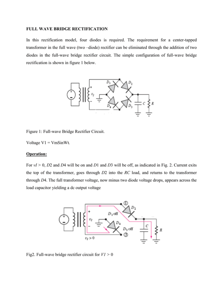
FULL WAVE BRIDGE RECTIFICATION In this rectification model, four diodes is required. The requirement for a center-tapped transformer in the full wave (two –diode) rectifier can be eliminated through the addition of two diodes in the full-wave bridge rectifier circuit. The simple configuration of full-wave bridge rectification is shown in figure 1 below. Figure 1: Full-wave Bridge Rectifier Circuit. Voltage V1 = VmSinWt. Operation: For vI > 0, D2 and D4 will be on and D1 and D3 will be off, as indicated in Fig. 2. Current exits the top of the transformer, goes through D2 into the RC load, and returns to the transformer through D4. The full transformer voltage, now minus two diode voltage drops, appears across the load capacitor yielding a dc output voltage Fig2. Full-wave bridge rectifier circuit for V1 > 0 𝑉𝑜𝑢𝑡 = 𝑉𝑚 − 2𝑉𝑑 …………………………………….eq1 The peak voltage at node 1, which represents the maximum reverse voltage appearing across D1, is equal to (Vm − Vd). Similarly, the peak reverse voltage across diode D4 is (Vm −2Vd)−(−Vd) = (Vm − Vd). For V1 < 0, D1 and D3 will be on and D2 and D4 will be off, as depicted in Fig. 3. Current leaves the bottom of the transformer, goes through D3 into the RC load, and back through D1 to the transformer. The full transformer voltage is again being utilized. The peak voltage at node 3 is now equal to (Vm − Vd) and is the maximum reverse voltage appearing across D4. Similarly, the peak reverse voltage across diode D2 is (Vm − 2Vd) − (−Vd) = (Vm − Vd). Fig 3: Full-wave bridge rectifier circuit for vI < 0. Important equations for full wave bridge rectifier to know as far as this class (Afe Babalola EE/C, 300L, 2014/2015) is concerned include the following; 1. 𝑉𝑜𝑢𝑡 = 𝑉𝑑𝑐 = 𝑉𝑚 − 2𝑉𝑑 2. 𝑉𝑟 = 3. 𝜃𝑐 = 𝑉𝑚 − 2𝑉𝑑 𝑇 2𝑅𝐶 2𝑉𝑟 𝑉𝑚 = ripple voltage, where 𝐼𝑑𝑐 = = conduction angle 𝑉𝑚 − 2𝑉𝑑 2𝑅 4. 𝜃𝑐 = 𝑤∆𝑇 5. 𝐼𝑝 = 𝐼𝑑𝑐 𝑇 ∆𝑇 = Peak repetitive current 6. 𝐼𝑠𝑢𝑟𝑔𝑒 = 𝑤𝐶𝑉𝑚 = surge current. 7. Peak Inverse Voltage, PIV = 𝑉𝑚 Example 1. Design a full wave bridge rectifier to provide a dc output voltage of 16 V with no more than 1 percent ripple at a load current of 3 A. Solution Teacher gives the solution in class. ASSIGNMENT Repeat the rectifier design assuming the use of a half-wave rectifier.


