Circuit Breaker Current & Energy Limiting Guide
advertisement
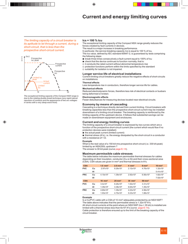
Current and energy limiting curves DB115719 The limiting capacity of a circuit breaker is its aptitude to let through a current, during a short-circuit, that is less than the prospective short-circuit current. (Isc) Prospective Isc peak Prospective current Prospective Isc Ics = 100 % Icu The exceptional limiting capacity of the Compact NSX range greatly reduces the forces created by fault currents in devices. The result is a major increase in breaking performance. In particular, the service breaking capacity Ics is equal to 100 % of Icu. The Ics value, defined by IEC standard 60947-2, is guaranteed by tests comprising the following steps: b break three times consecutively a fault current equal to 100% of Icu b check that the device continues to function normally, that is: v it conducts the rated current without abnormal temperature rise v protection functions perform within the limits specified by the standard v suitability for isolation is not impaired. Longer service life of electrical installations Current-limiting circuit breakers greatly reduce the negative effects of short-circuits on installations. Limited Isc peak Actual current Limited Isc Thermal effects Less temperature rise in conductors, therefore longer service life for cables. (t) The exceptional limiting capacity of the Compact NSX range is due to the rotating double-break technique (very rapid natural repulsion of contacts and the appearance of two arc voltages in-series with a very steep wave front). Mechanical effects Reduced electrodynamic forces, therefore less risk of electrical contacts or busbars being deformed or broken. Electromagnetic effects Fewer disturbances for measuring devices located near electrical circuits. Economy by means of cascading Cascading is a technique directly derived from current limiting. Circuit breakers with breaking capacities less than the prospective short-circuit current may be installed downstream of a limiting circuit breaker. The breaking capacity is reinforced by the limiting capacity of the upstream device. It follows that substantial savings can be made on downstream equipment and enclosures. Current and energy limiting curves The limiting capacity of a circuit breaker is expressed by two curves which are a function of the prospective short-circuit current (the current which would flow if no protection devices were installed): b the actual peak current (limited current) b thermal stress (A2s), i.e. the energy dissipated by the short-circuit in a conductor with a resistance of 1 Ω. Example What is the real value of a 150 kA rms prospective short-circuit (i.e. 330 kA peak) limited by an NSX250L upstream ? The answer is 30 kA peak (curve page E-14). Maximum permissible cable stresses The table below indicates the maximum permissible thermal stresses for cables depending on their insulation, conductor (Cu or Al) and their cross-sectional area (CSA). CSA values are given in mm² and thermal stresses in A2s. CSA PVC Cu 1.5 mm² 2.97x10⁴ 2.5 mm² 8.26x10⁴ 4 mm² 2.12x10⁵ 6 mm² 4.76x10⁵ 10 mm² 1.32x10⁶ PRC Cu 4.10x10⁴ 1.39x10⁵ 2.92x10⁵ 6.56x10⁵ 1.82x10⁶ 16 mm² 25 mm² 35 mm² 50 mm² Cu 3.4x10⁶ Al Al 5.41x10⁵ Al CSA PVC PRC 7.52x10⁵ 8.26x10⁶ 1.62x10⁷ 3.31x10⁷ 1.39x10 6 3.38x10 6 6.64x10 6 1.35x10⁷ Cu 4.69x10 6 1.39x10 7 2.23x10 7 4.56x10⁷ Al 1.93x10⁶ 9.23x10⁶ 1.88x10⁷ 4.70x10⁶ Example Is a Cu/PVC cable with a CSA of 10 mm² adequately protected by an NSX160F? The table above indicates that the permissible stress is 1.32x10⁶ A2s. All short-circuit currents at the point where an NSX160F (Icu = 35 kA) is installed are limited with a thermal stress less than 6x10⁵ A2s (curve page E-14). Cable protection is therefore ensured up to the limit of the breaking capacity of the circuit breaker. E-13

