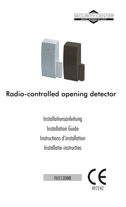
Radio-controlled opening detector
advertisement

Radio-controlled opening detector Installationsanleitung Installation Guide Instructions d’installation Installatie-instructies FU5120WB 497242 Fig. 1 Fig. 2 Fig. 3 Fig. 4 Fig. 5 2 Preface Dear Customer, Thank you for purchasing this radio-controlled opening detector. You made the right decision in choosing this state-of-the-art technology, which complies with the current standards of domestic and European regulations. The CE has been proven and all related certifications are available from the manufacturer upon request. To maintain this status and to guarantee safe operation, it is your obligation to observe these operating instructions! In the event of questions, please contact your local specialist dealer. This radio-controlled opening detector is used for monitoring doors and windows. It works contact-free and monitors the state (open/closed) of a door or window and reports this to a radio alarm system. ! Read carefully the notes and advice in these operating instructions! If you do not follow these instructions, your guarantee claim becomes invalid! We can accept no liability for the consequences! No part of the product may be changed or modified in any way. 3 Fig. 1 Number 1 2 3 4 5 6 7 8 9 10 Name Fixing screw Jumper connector LK4 Jumper connector LK2 Magnet switch Jumper connector LK3 Jumper connector LK1 Battery Screw clamp block Tamper protection, lid LED LED Flashing: 4x flashing: Off: Program mode Transmit Normal LK1, LK3 Operating mode of external contact LK 1 LK 3 NC NO Vibrator LK2 Internal contact Off On 4 LK4 Programming On Off Installation 1. Open the casing by loosening the screw and then removing the cover. 2. Remove the PCB from the housing: Loosen screw (Fig. 1, Pos. 1), then lift out the PCB. 3. Fig. 2, Pos. 1,2: Positions of screws for fixing the housing 3.1. Hold the housing base against the frame of the door or window. 3.2. Mark the screw positions for fixing. Note the measurements specified in Fig. 3. 3.3. The best position for the opening detector is the upper corner of the window/door frame – see Fig. 4. You can also swap the detector and magnet positions. In this case, however, you have to fit the detector upside down. 4. Fix the housing rear to the marked position with two screws. The rear of the housing must lie flat on the surface so that the wall removal contact is closed. 5. Replace the PCB in the housing. 6. Fix the magnet as shown in Fig. 3. 5 Learning 1. Switch your radio alarm equipment / radio receiver to learn mode. See the system instructions for advice on this. 2. Radio variant: Insert a battery in the radio-controlled opening detector (Fig. 1, Pos. 7). Check for correct polarity. Hold the tamper protection for the front panel (Pos. 9, Fig.1) and the wall removal contact down with the finger and release it several time to trigger radio signals. IR variant: Point the LED of the opening detector at the IR receiver of the radio extension (RFX). Now trigger the tamper contact of the opening detector. 3. Make sure that the opening detector is recognised by your radio alarm equipment / radio receiver and then close the case. Connecting external contacts You can connect more than one external detector with NC contacts to this opening detector. Two or more devices must be serially connected. The cable length must not exceed 10 m. Connect the external devices to the screw clamps marked “Alarm” and “TAMP” on the PCB (see Fig. 5). Teaching external contacts The external contacts of the opening detector are trained for an extra zone of the system: 6 1. Switch your radio alarm equipment to learn mode. See the system instructions for advice on this. 1.1. Trigger the external detector. 1.2. Check that the alarm system has recognised the detector. Using detectors as radio modules You can also use this radio magnet contact as a radio module. 1. Close the jumper connection LK2 (Fig.1, Pos.3) to deactivate the internal magnet contact. 2. You can use the reed connectors on the screw clamp block for detectors without tamper protection (e.g. gas sensors). 2.1. Connect the detectors to the reed contacts. 2.2. Switch your radio alarm equipment to learn mode. See the system instructions for advice on this. 2.3. Trigger the detector. 2.4. Check that the alarm system has recognised the detector. 2.5. The tamper protection (lid and wall) of the opening detector are active in this trained zone. 3. Connect further detectors to the clamps marked “Alarm” and train them for this zone (see “Connecting external contacts” and “Teaching external contacts”. 7 Connecting vibration detector Connect the alarm contacts of the detector to the “ALARM” contacts (see Fig. 5) and the tamper contacts to “TAMPER”. If no tamper connections are present, jump the contacts in the radio detector. You can train the detector for an extra zone of the alarm system as described in “Teaching external contacts”. 1. Vibration detector programming You can adjust the sensitivity of the vibration detector. 1.1. Connect contact LK3 and leave LK1 open (Fig. 1, Pos. 5 and 6). 1.2. With the plug, connect the two pins of jumper LK4 (Fig. 1, Pos. 2). 1.3. Move the vibration detector sufficiently to trigger at the intended level. 1.4. Repeat the movement 4 or 5 times to get a better result. 1.5. Remove the jumper from LK4 and connect it to one pin only. 2. Activating/deactivating LED Make sure that the opening detector is not in programming mode. 3. Activating LED 3.1. Plug a jumper over jumper LK1 and one over LK3. 3.2. Short-circuit LK4 for max. one second with a jumper and then remove the jumper: the LED is now activated. 8 3.3. Restore the original position of the jumper. 4. Deactivating LED 4.1. Short-circuit LK1 only. 4.2. Short-circuit LK4 for max. one second with a jumper and then remove the jumper. The LED is now deactivated. 4.3. Restore the original position of the jumper. Closing the case Place the cover on the base and fix it with the screw. Technical Data Power supply: 3V Li/MnO2 Battery size: CR2 Avgerage current: 0,03A Battery life time: up to 36 month Environmental class: I (-10-+55°C) Security grade: II INCERT-No.: CXXXXXX Housing material: Flame retardant ABS Weight: ca. 53g Dimens. HxWxD mm: 33x89x29 9


