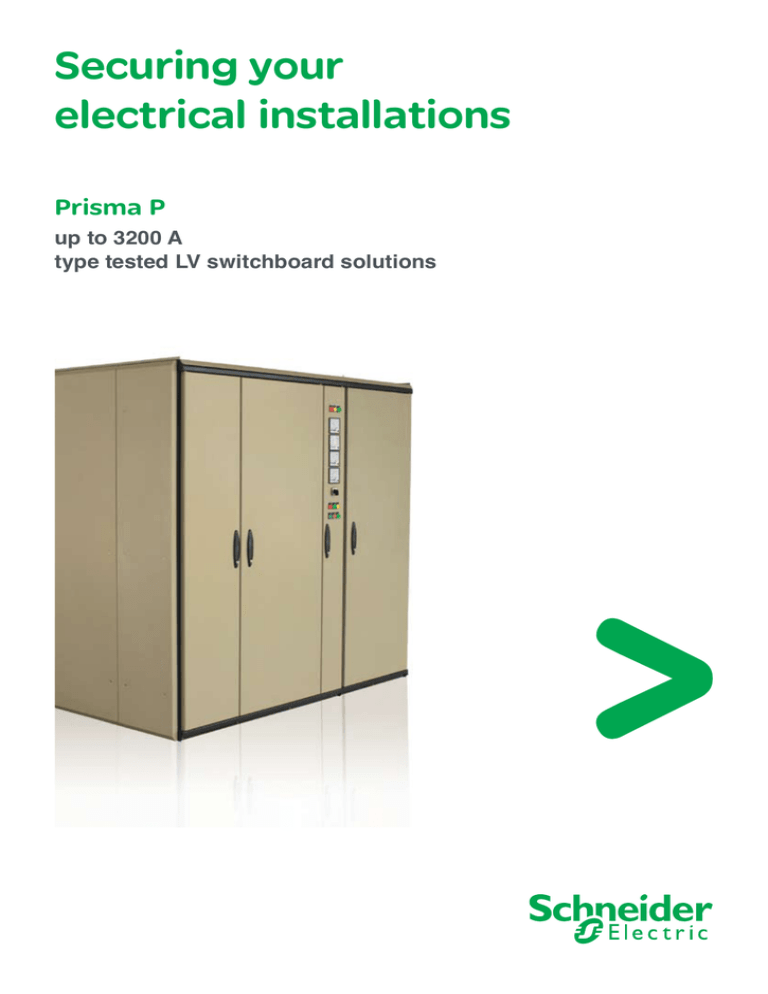
Securing your electrical installations
advertisement

Securing your electrical installations Prisma P up to 3200 A type tested LV switchboard solutions Table of contents Electrical switchboards up to 3200 A .................................................................... 3 A complete safety of type tests .................................................................... 4 Choice of Prisma P enclosures .................................................................... 5 Prisma P several configurations .................................................................... 6 Schneider products inside Prisma .................................................................... 8 General technical information .................................................................... 9 Electrical switchboards Up to 3200 A With the Prisma P system, Schneider Electric proposes highperformance technical solutions, with enhanced robusteness, looks and aesthetics to produce low voltage electrical switchboards up to 3200 A, in commercial and industrial buildings. From the simplest through to the highly sophisticated, these simple yet dependable solutions are tailored to meet customers’ needs. The modular building blocks are designed with a strict eye on details to ensure a professional result. Prisma switchboards capitalize on the experience gained over 30 years, during which thousands of switchboards have been built and operated. Prisma electrical switchboards For a dependable electrical installation Total compatibility between Schneider Electric switchgear devices and the Prisma system helps build dependability into every electrical installation, that has been validated by type tests in compliance with standard IEC 60439-1. An electrical installation capable of evolving Modular in structure, Prisma can keep pace with evolving switchboard needs and integrate new functional units as required. Maintenance operations are fast and easy with total access to all switchgear devices. Total safety for users Switchgear devices are installed behind a protective front plate that leaves only the operating handle visible. General characteristics Enclosure ■ material: sheet steel, anti-corrosion painting ■ surface treatment: anti-corrosion coating, thermal polymerised polyester-epoxy powder. Colour Prisma beige / dark grey. ■ busbar insulating supports: all plastic parts withstand fire or excessive heat caused by internal electrical phenomena, as per IEC 695-2.1: 960° 30s/30s for supports for live metal parts. Building up installations Functional Prisma components can be used to build switchgear assemblies in compliance with: standards IEC 60439-1. ■ with the following electrical specifications: p rated insulation voltage for the main busbars: 1000 V p rated current 3200 A p peak withstand current: Ipk 187 k p short time withstand current: Icw 85 kA rms / 1sec p frequency 50 / 60 Hz. Prisma P functional system With the Prisma P cubicles, the same components, whether for switchgear installation, current distribution, cable running, etc., may be installed depending on the installation site, with the following varieties: IP 31, IP 54 may be dismantled may be joined side by side 4 basic widths: 700, 900, 1100, 1300 mm 2 basic depths: 400, 600 mm and 2 back to back depths: 800, 1000 mm ■ frame height: 2000 mm ■ ■ ■ ■ ■ 3 A complete safety of type tests A dual guarantee The Prisma switchboard, tested and produced according to standards, offers its operator a dual guarantee: ■ use of dependable components, with platform tested assemblies, ■ rigorous final inspection. IEC standard 60439-1 Schneider Electric offers Prisma switchboard series on which the 7 type tests have been conducted. defines 7 type tests and Schneider Electric’s Certified Prisma Partners, who assemble & test the Prisma switchboard, also attest to quality by carrying out the 3 individual routine tests specified in the international standard IEC 60439-1. which offer the best These 10 tests guarantee the switchboard’s operational safety, as well as the safety of people and equipment from switchboard commissioning onwards and throughout switchboard service life. 3 individual routine tests long term safety and reliability guarantees to electrical installation. 10 tests to certify installation quality ■ 7 type tests conducted on Prisma P which are: 1- temperature rise limit, 2- dielectric properties, 3- short-circuit withstand, 4- protection circuit efficency, 5- clearances and creepage distance, 6- mechanical operation, 7- degree of protection. tion Certifica This is that XXX ■ Certified Prisma Partners attest to the quality of each switchboard by carrying out the 3 individual routine tests specified in the international standard IEC 60439-1: 1- cabling and electrical operation, 2- dielectric testing, 3- protection measures. 7 type tests conducted in the laboratory + = 4 to certify 3 routine tests carried out by Certified Prisma Partner a 100 % validated switchboard in Egypt ctr ic mbly and der Ele Schneint for the design, asse ibution rtner for agreeme power distr voltage boration isma Pa em: is a Pr technical colla type tested low functional syst a wing and has trol of the the follo quality con oards using switchb a ranges Prism 39-1 and IEC 604 g ent as per tric incorporatin r equipm tests thei of Schneider Elec mbles & tices igns, asse ign prac XXX des the latest des in line with Abbal FredericDirector Africa Managing North East Egypt & 2006 on: 01/01/ 2006 Issued 31/12/ Valid thru: Building a New Electr ic World Choice of Prisma P enclosures Depth = 400 mm cubicles (1) 700 700 200 W = 900 mm W = 700 mm (1) 200 70 700 200 or 700 400 80 W = 1100 mm (1) 200 700 (1) The cable or bar duct can be installed on the right or left side of the frame in which the devices are mounted. 400 W = 1300 mm (1) Depth = 600 mm cubicles 700 700 W = 700 mm 200 W = 900 mm (1) 200 700 200 or 700 400 W = 1100 mm (1) 200 700 (1) The cable or bar duct can be installed on the right or left side of the frame in which the devices are mounted. 400 W = 1300 mm Depth = 800 / 1000 mm (back to back) cubicles A depth of 800 or 1000 is obtained by installing the basic frames in all existing widths back to back. In the back to back layout, cubicle sides are covered by normal end panels according to the combination. D = 800 mm D = 1000 mm Two basic frames side by side Two basic frames of different depths can be joined directly together. + Two basic frames 5 Prisma P several configurations Upper horizontal basbar Breaker with incoming top busduct. Breaker with incoming top cables. 6 Incoming circuit breaker Breaker with bottom cable connection. Outgoing functional units Cable compartment Cable tie bars in width 200 and 400 mm. 7 Schneider products inside Prisma Prisma P switchboards are leveraged by an unparalleled lineup of products. These products are the building bricks of various solutions for electric distribution, power monitoring, motor control and protection and power factor correction. High and medium power busbar trunking Canalis Power metering & monitoring unit PowerLogic PM… Air circuit breaker 630 A … 1600 A Masterpact NT Molded case circuit breaker 100 A … 3200 A Compact NS We are committed to developing competitive, compatible products that are easy to install & operate. Our products and systems optimize electrical installations, make them safer and more flexible, while complying with prevailing standards. 8 Air circuit breaker 800 A … 3200 A Masterpact NW Molded case circuit breaker 100 A … 400 A EasyPact DIN rail products Miniature circuit breakers, residual current devices, earth leakage protection, etc. multi9 Thermal magnetic circuit breaker GV2-ME, GV2-P Monitoring relays Zelio Control RM‥ Low voltage capacitor banks Varplus 2 LV power factor controllers Varlogic General technical information Connection by cables Practical rules: Schneider Electric recommends cabling according to the circuit breaker rating. The following tables take into account the installation conditions related to the type of device (permissible temperatures near the connection terminals, etc.). They ensure consistency with the temperature derating values of the installed devices. Connection of circuit-breaker by cables ■ copper cables. Device Section (mm2) NS100 25 NS160 50 NS250 NS400/NS630 95 Permissible current with cables secured individually Current (A) IP 31 14 25 29 39 55 77 100 Cable Section (mm2) 1.5 2.5 4 6 10 16 25 straps or bars 125 150 190 230 35 50 70 95 Permissible current with cables secured in bundles Current (A) IP 31 12 20 24 33 50 Cable Section (mm2) 1.5 2.5 4 6 10 70 93 120 16 25 35 Connection of other devices by cables ■ copper cables. Permissible current with cables secured individually Current (A) IP 31 12 21 26 35 50 70 90 Cable Section (mm2) 1.5 2.5 4 6 10 16 25 Permissible current with cables secured in bundles Current (A) IP 31 10 19 22 30 46 Cable Section (mm2) 1.5 2.5 4 6 10 Sizing of protective conductor PE 115 135 176 210 35 50 70 95 63 84 103 16 25 35 Optimised method: Use the calculation formula given by standard IEC 60439-1: SPE = I2t k ■ SPE: cross-sectional area of PE in mm2 ■ I2: value of the phase-to-earth fault current = 60% of the value of the phase-to-phase fault current (standard IEC 60438-1 §8.2.4.2). ■ t: duration of the fault current in seconds ■ k: a factor depending on the conductor material. k = 143 for a PVCinsulated copper PE conductor. Simplified method (based on the above formula): ■ Use the table below. ■ Depending on the Isc of the device, determine the cross-sectional area of the PE conductor. Cross-sectional area of the PE conductor (mm) Isc 40 kA 40 < Isc < 50 kA Isc u 50 kA Masterpact NWH3 with a 0.5 sec. time delay 1 bar 25 x 5 1 bar 50 x 5 1 bar 50 x 5 Other Schneider Electric device 1 bar 25 x 5 1 bar 25 x 5 1 bar 50 x 5 9 General technical information Degree of protection IP code Standard IEC 60364-3 lists and codes a large number of external influences to which an electrical installation may be subjected: presence of water, presence of solid bodies, risk of impacts, vibrations, presence of corrosive substances. These influences are exerted with an intensity varying according to installation conditions: the presence of water may be simply a few drops falling…or complete immersion. Standard IEC 60529 indicates the degrees of protection provided by an enclosure for electrical devices against access to hazardous parts, against penetration of solid foreign objects and against penetration of water. 1st digit Protection against ingress of solid objects 1 Protected against Ø 50 mm 2 Protected against Ø 12,5 mm solid foreign objects larger than 50 mm solid foreign objects larger than 12.5 mm 3 Protected against solid foreign objects larger than 2.5 mm 4 Protected against solid foreign objects larger than 1 mm These standards do not apply for the protection against the risks of explosion or conditions such a humidity, corrosive vapour, fungus or vermin. The IP code is made up of two digits and can include an additional letter when the actual protection against access to the hazardous parts is better than that indicated by the first digit. The first digit characterises the protection provided by the enclosure against the ingress of solid foreign objects. The second digit characterises the protection provided against the ingress of water with harmful effects. 2nd digit Protection against ingress of water 1 Protected against vertically falling water drops (condensation) Ø 2,5 mm Ø 1 mm 2 Protected against vertically falling water drops when enclosure tilted up to 15° 3 Protected against spraying water up to 60° from vertical 4 Protected against splashing water from all directions 5 Protected against dust 5 Protected against 6 Dust tight 6 Protected against (dust protected) water jets from all directions powerful water jets from all directions 7 Protected against the effects of temporary immersion in water 8 Protected against the effects of continuous immersion in water 10 15 60 Schneider Electric SEE 86048 / E NE Africa & Egypt Head Office 68, Tayaran st., Nasr City, Cairo, Egypt. P.O. Box 2658 El Horreya. Tel : + 202 24 01 01 19 Fax: + 202 22 61 89 08 http://www.schneider-electric.com.eg Customer Care Center (CCC) Hotline: 19775 email: customer.care@eg.schneider-electric.com Design & production: Communication - SEE Printing: Trust Advertising co. As standard specifications and designs change from time to time, please ask for confirmation of the information given in this publication.


