"High Frequency Ceramic Solutions"
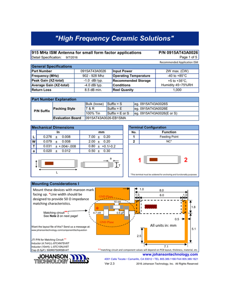
915 MHz ISM Antenna for small form factor applications
Detail Specification:
P/N 0915AT43A0026
Page 1 of 5
9/7/2016
Recommended Application ISM
General Specifications
Part Number
Frequency (MHz)
Peak Gain (XZ-total)
Average Gain (XZ-total)
Return Loss
0915AT43A0026
902 - 928 Mhz
-1.0 dBi typ.
-4.0 dBi typ.
8.5 dB min.
Input Power
Operating Temperature
Recommended Storage
Conditions
Reel Quanity
2W max. (CW)
-40 to +85°C
+5 to +35°C,
Humidity 45~75%RH
1,000
Part Number Explanation
P/N Suffix
Packing Style
Evaluation Board
Bulk (loose) Suffix = S
T&R
Suffix = E
100% Tin
Suffix = E or S
0915AT43A0026-EB1SMA
Mechanical Dimensions
L
W
T
a
0.276
0.079
0.031
0.020
In
± 0.008
± 0.008
± +.004/-.008
± 0.012
7.00
2.00
0.80
0.50
eg. 0915AT43A0026S
eg. 0915AT43A0026E
eg. 0915AT43A0026(E or S)
Terminal Configuration
No.
Function
Feeding Point
1
NC*
2
mm
± 0.20
± 0.20
± +0.1/-0.2
± 0.30
a
2
1
T
L
*This terminal must be soldered for anchoring and functionality purposes
Mounting Considerations I
Mount these devices with maroon mark
facing up. *Line width should be
designed to provide 50 Ω impedance
matching characteristics.
Matching circuit**:
See Note 2 on next page!
1.0
1.0
GND Plane
8.0
1.0
6.0
10 nH
1.8
*
4.7 nH
0.5 pF
0.5
GND Plane
All units in: mm
Want the layout file of this? Send us a message at:
5.1
www.johansontechnology.com/component/techquestion
2.5
JTI P/N for Matching Circuit:**
Inductor (4.7nH):L-07C4N7SV6T
Inductor (10nH): L-07C10NJV6T
Cap (0.5pF): 500R07S0R5BV4T
7.1
**matching circuit and component values will depend on PCB layout, thickness, material, etc.
www.johansontechnology.com
4001 Calle Tecate • Camarillo, CA 93012 • TEL 805.389.1166 FAX 805.389.1821
Ver 2.3
2016 Johanson Technology, Inc. All Rights Reserved
"High Frequency Ceramic Solutions"
915 MHz ISM Antenna for small form factor applications
Detail Specification:
P/N 0915AT43A0026
Page 2 of 5
9/7/2016
Recommended Application ISM
Mounting Considerations II
9.5mm
40mm
Johanson Test Board
(orderable) p/n:
0915AT43A0026-EB1SMA
50Feed Line
(make sure
proper
calculation are
applied to
achieve this.
20mm
GND Plane
Yellow areacomplete GND
and layer
clearance free
of metal below
and above.
GND Plane
19mm (can be shortened as needed,
won't influence performance)
**Note 2: It is recommended that the designer leave available slots for a "pi" (or shunt-series-shunt)
network. The antenna matching network values above are used when antenna is mounted on
Johanson's evaluation board. The matching values on client’s PCB will be different. Go to:
www.johansontechnology.com/tuning and see how to obtain the new values. If you need further
help, such as needing the layout file of the above, contact our RF Applications Eng. Team at:
www.johansontechnology.com/ask-a-question
Return Loss (with matching)
0
-5
m1
freq=902.0MHz
dB(S(1,1))=-11.217
m2
freq=928.0MHz
dB(S(1,1))=-11.807
m3
freq=915.0MHz
dB(S(1,1))=-43.257
m1m2
-10
dB(S(1,1))
-15
-20
-25
-30
-35
-40
-45
0.5
m3
0.6
0.7
0.8
0.9
1.0
1.1
1.2
1.3
freq, GHz
Johanson Technology, Inc. reserves the right to make design changes without notice. Please confirm the specifications
and delivery conditions when placing your order. All sales are subject to Johanson Technology, Inc. terms and conditions.
www.johansontechnology.com
4001 Calle Tecate • Camarillo, CA 93012 • TEL 805.389.1166 FAX 805.389.1821
Ver 2.3
2016 Johanson Technology, Inc. All Rights Reserved
"High Frequency Ceramic Solutions"
915 MHz ISM Antenna for small form factor applications
Detail Specification:
P/N 0915AT43A0026
Page 2 of 5
9/7/2016
Recommended Application ISM
Mounting Considerations III
We have conducted internal studies to show that the following corner placements provide antenna efficiency
results with minimal detrimental effects.
11mm
10mm
3mm
11mm
10mm
3mm
Yellow areacomplete GND
and layer
clearance free
of metal below
and above.
42mm
42mm
GND
50Feed Line
(make sure
proper
calculation are
applied to
achieve this.
GND Plane
26mm
26mm
8.0
Note: It is recommended that the designer leave
available slots for a "pi" (or shunt-series-shunt)
network. The antenna matching network values above
are used when antenna is mounted on Johanson's
evaluation board. The matching values on client’s PCB
will be different. Go to:
www.johansontechnology.com/tuning and see how to
obtain the new values. If you need further help, such as
needing the layout file of the above, contact our RF
Applications Eng. Team at:
www.johansontechnology.com/ask-a-question
1.0
6.0
1.0
1.8
0.5
5.1
2.5
7.1
Johanson Technology, Inc. reserves the right to make design changes without notice. Please confirm the specifications
and delivery conditions when placing your order. All sales are subject to Johanson Technology, Inc. terms and conditions.
www.johansontechnology.com
4001 Calle Tecate • Camarillo, CA 93012 • TEL 805.389.1166 FAX 805.389.1821
Ver 2.3
2016 Johanson Technology, Inc. All Rights Reserved
"High Frequency Ceramic Solutions"
915 MHz ISM Antenna for small form factor applications
Detail Specification:
P/N 0915AT43A0026
Page 4 of 5
9/7/2016
Recommended Application ISM
Typical Radiation Performance @ 25° C using 0915AT43A0026-EB1SMA
Typical Radiation Patterns
XY-V/XY-H
Z
)
XY cut @915MHz
Vertical
Horizontal
180°
X
270°
90°
Y
0°
XY-cut scanning direction
XZ-V/XZ-H
XZ cut @915MHz
Vertical
Horizontal
Y
180°
X
270°
90°
Z
0°
YZ-V/YZ-H
XZ-cut scanning direction
YZ cut @915MHz
Vertical
Horizontal
)
X
180°
Y
270°
90°
Z
0°
YZ-cut scanning direction
Johanson Technology, Inc. reserves the right to make design changes without notice. Please confirm the specifications
and delivery conditions when placing your order. All sales are subject to Johanson Technology, Inc. terms and conditions.
www.johansontechnology.com
4001 Calle Tecate • Camarillo, CA 93012 • TEL 805.389.1166 FAX 805.389.1821
Ver 2.3
2016 Johanson Technology, Inc. All Rights Reserved
"High Frequency Ceramic Solutions"
915 MHz ISM Antenna for small form factor applications
P/N 0915AT43A0026
Page 5 of 5
Detail Specification: 9/7/2016
More SMD Chip Antennas at:
www.johansontechnology.com/antennas
Packaging information
www.johansontechnology.com/tape-reel-packaging
Soldering Information
www.johansontechnology.com/typical-soldering-profile
Antenna layout and tuning techniques (How to obtain the new antenna matching values)
www.johansontechnology.com/tuning
Antenna layout review, tuning, and characterization services
www.johansontechnology.com/ipc-antenna-services
RoHS Compliance
www.johansontechnology.com/rohs-compliance
MSL Info
www.johansontechnology.com/msl-rating
Johanson Technology, Inc. reserves the right to make design changes without notice. Please confirm the specifications
and delivery conditions when placing your order. All sales are subject to Johanson Technology, Inc. terms and conditions.
www.johansontechnology.com
4001 Calle Tecate • Camarillo, CA 93012 • TEL 805.389.1166 FAX 805.389.1821
Ver 2.3
2016 Johanson Technology, Inc. All Rights Reserved


