Industrial Exit Signs NEMA Series CH-40500
advertisement
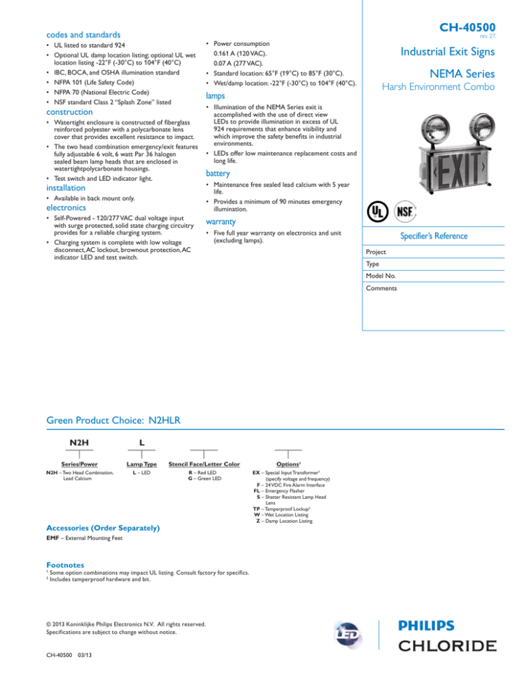
CH-40500 codes and standards rev. 27, • UL listed to standard 924 • Optional UL damp location listing; optional UL wet location listing -22°F (-30°C) to 104°F (40°C) • IBC, BOCA, and OSHA illumination standard • NFPA 101 (Life Safety Code) • NFPA 70 (National Electric Code) • NSF standard Class 2 “Splash Zone” listed construction • Watertight enclosure is constructed of fiberglass reinforced polyester with a polycarbonate lens cover that provides excellent resistance to impact. • The two head combination emergency/exit features fully adjustable 6 volt, 6 watt Par 36 halogen sealed beam lamp heads that are enclosed in watertightpolycarbonate housings. • Test switch and LED indicator light. installation • Available in back mount only. electronics • Self-Powered - 120/277 VAC dual voltage input with surge protected, solid state charging circuitry provides for a reliable charging system. • Charging system is complete with low voltage disconnect, AC lockout, brownout protection, AC indicator LED and test switch. • • • Power consumption 0.161 A (120 VAC). 0.07 A (277 VAC). Standard location: 65°F (19°C) to 85°F (30°C). Wet/damp location: -22°F (-30°C) to 104°F (40°C). Industrial Exit Signs NEMA Series Harsh Environment Combo lamps • Illumination of the NEMA Series exit is accomplished with the use of direct view LEDs to provide illumination in excess of UL 924 requirements that enhance visibility and which improve the safety benefits in industrial environments. • LEDs offer low maintenance replacement costs and long life. battery • Maintenance free sealed lead calcium with 5 year life. • Provides a minimum of 90 minutes emergency illumination. warranty • Five full year warranty on electronics and unit (excluding lamps). Specifier’s Reference Project Type Model No. Comments Green Product Choice: N2HLR N2H L Series/Power Lamp Type N2H – Two Head Combination, Lead Calcium L – LED Stencil Face/Letter Color R – Red LED G – Green LED Accessories (Order Separately) Options1 EX – Special Input Transformer1 (specify voltage and frequency) F – 24 VDC Fire Alarm Interface FL – Emergency Flasher S – Shatter Resistant Lamp Head Lens TP – Tamperproof Lockup2 W – Wet Location Listing Z – Damp Location Listing EMF – External Mounting Feet Footnotes 1 2 Some option combinations may impact UL listing. Consult factory for specifics. Includes tamperproof hardware and bit. © 2013 Koninklijke Philips Electronics N.V. All rights reserved. Specifications are subject to change without notice. CH-40500 03/13 CH-40500 options NEMA Series Harsh Environment Combo rev. 27, • TP – The tamperproof option provides torx T15 hardware with center pin reject and the bit required to secure and access the equipment for future servicing. • WL – UL wet location listed for use in temperatures ranging from -22°F to 104°F. • Z – UL damp location listed for use in temperatures ranging from -22°F to 104°F. • EX – The special input transformer option allows for input voltage and frequencies beyond the standard 120/277 VAC, 60 Hz input. • F – This option provides a two-wire harness for the electrical connection to the fire control panel. Should the fire panel activate an alarm, the exit sign will flash at a rate of approximately 50% duty cycle. • FL – This option causes the exit sign to flash when the sign is operating under battery power. The flashing rate is approximately a 50% duty cycle. dimensions 13.5" (34.3cm) 7.2" (18.3cm) 11.8" (30.0cm) 6.6" (16.8cm) performance Meets Life Safety Code illumination standard; average of 1.0 FC, no point less than 0.1 FC, max to min ratio of 40:1. Assumes open space with no obstructions, mounting height: 8' and reflectances: 80/50/20. Analysis based on independently tested photometrics. Wall mounted 8' AFF, 6 V 6 W PAR 36 Lamps Represented 1 FC Average 8 ft. 0.2 0.1 0.1 0.2 0.1 0.2 0.2 0.4 0.2 0.2 0.2 0.2 0.2 0.5 0.7 0.5 0.2 0.5 0.4 0.3 0.9 1.2 0.8 0.3 0.9 0.5 0.6 1.5 1.5 1.6 1.0 0.3 0.6 1.1 1.9 1.7 1.1 0.3 1.8 0.4 1.3 2.1 1.3 0.9 0.2 1.8 0.3 1.3 1.5 0.9 0.7 0.2 1.3 0.3 1.0 1.0 0.4 0.4 0.2 16 ft. Average initial footcandles at floor = 1.06 Maximum initial footcandles at floor = 2.1 Minimum initial footcandles at floor = 0.4 Maximum to minimum ratio = 5.25 0.8 0.3 0.7 0.5 0.4 0.4 0.2 0.5 0.3 0.4 0.5 0.4 0.3 0.2 0.5 0.3 0.4 0.5 0.4 0.4 0.2 0.5 0.3 0.4 0.5 0.8 0.5 0.3 0.5 0.4 0.4 1.0 1.3 0.8 0.3 1.0 0.5 0.7 1.5 1.7 1.1 0.3 1.4 0.5 1.0 2.1 1.6 1.1 0.2 1.9 0.5 1.3 1.9 1.2 0.9 0.2 1.7 0.3 1.3 1.6 0.8 0.5 0.1 1.4 0.2 0.9 0.3 0.1 1.0 0.8 0.4 0.1 0.6 0.5 0.2 0.4 0.2 0.3 0.2 0.2 0.2 4 ft. © 2013 Koninklijke Philips Electronics N.V. All rights reserved. Specifications are subject to change without notice. Philips Lighting Company 200 Franklin Square Drive Somerset, NJ 08873 Phone: 855-486-2216 Philips Lighting Company 281 Hillmount Road Markham ON, Canada L6C 2S3 Phone: 800-668-9008 CH-40500 03/13 www.philips.com/luminaires www.philips.com/luminaires
