Dry-Type Transformers
Howard Industries, Inc.
ISO-9001 Certified
Introduction
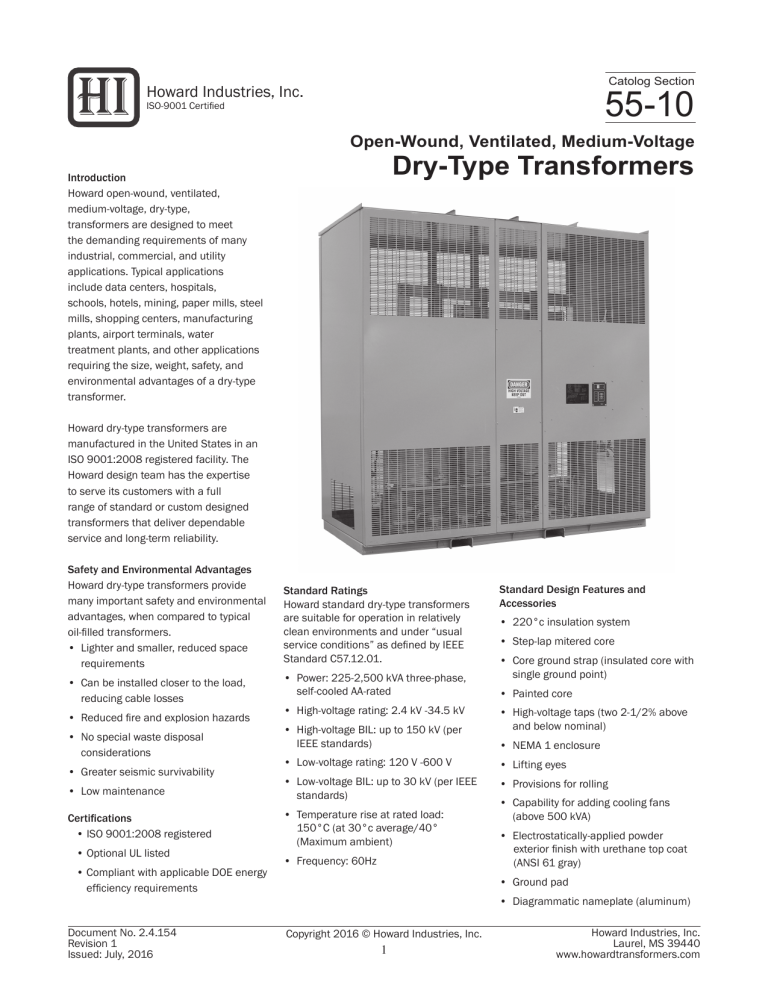
Howard open-wound, ventilated, medium-voltage, dry-type, transformers are designed to meet the demanding requirements of many industrial, commercial, and utility applications. Typical applications include data centers, hospitals, schools, hotels, mining, paper mills, steel mills, shopping centers, manufacturing plants, airport terminals, water treatment plants, and other applications requiring the size, weight, safety, and environmental advantages of a dry-type transformer.
Howard dry-type transformers are manufactured in the United States in an
ISO 9001:2008 registered facility. The
Howard design team has the expertise to serve its customers with a full range of standard or custom designed transformers that deliver dependable service and long-term reliability.
Safety and Environmental Advantages
Howard dry-type transformers provide many important safety and environmental advantages, when compared to typical oil-filled transformers.
• Lighter and smaller, reduced space requirements
• Can be installed closer to the load, reducing cable losses
• Reduced fire and explosion hazards
• No special waste disposal considerations
• Greater seismic survivability
• Low maintenance
Certifications
• ISO 9001:2008 registered
• Optional UL listed
• Compliant with applicable DOE energy efficiency requirements
Standard Ratings
Howard standard dry-type transformers are suitable for operation in relatively clean environments and under “usual service conditions” as defined by IEEE
Standard C57.12.01.
• Power: 225-2,500 kVA three-phase, self-cooled AA-rated
• High-voltage rating: 2.4 kV -34.5 kV
• High-voltage BIL: up to 150 kV (per
IEEE standards)
• Low-voltage rating: 120 V -600 V
• Low-voltage BIL: up to 30 kV (per IEEE standards)
• Temperature rise at rated load:
150°C (at 30°c average/40°
(Maximum ambient)
• Frequency: 60Hz
Document No. 2.4.154
Revision 1
Issued: July, 2016
55-10
Open-Wound, Ventilated, Medium-Voltage
Dry-Type Transformers
Copyright 2016 © Howard Industries, Inc.
1
Standard Design Features and
Accessories
• 220°c insulation system
• Step-lap mitered core
• Core ground strap (insulated core with single ground point)
• Painted core
• High-voltage taps (two 2-1/2% above and below nominal)
• NEMA 1 enclosure
• Lifting eyes
• Provisions for rolling
• Capability for adding cooling fans
(above 500 kVA)
• Electrostatically-applied powder
exterior finish with urethane top coat
(ANSI 61 gray)
• Ground pad
• Diagrammatic nameplate (aluminum)
Howard Industries, Inc.
Laurel, MS 39440 www.howardtransformers.com
55-10 Medium-Voltage Dry-Type Transformer
Optional Design Features and
Accessories
Howard excels at producing custom designs for non-standard applications and can offer numerous optional features and accessories to suit a customer’s special requirements.
• Custom designs for special applications
• Loss optimization for lower total owning cost
• Higher efficiency requirement
• 50 Hz. frequency
• Non-standard ambient conditions
• Non-standard BIL level
• Non-standard altitude requirement
• Non-standard sound requirement
• Higher overload capacity
• Low X/R ratios
• K- factor rated (K1, K4, K9)
• Special seismic qualification
• Reduced vibration and vibration isolation
• Retrofit designs
• 80°C or 115°C temperature rise
• Automatic fan cooling package (FA rated)
• Digital temperature monitor
• Copper bus and windings
• Wye-wye connected windings
• Provisions for parallel operation
• Ground bus (copper)
• Medium-voltage interrupter switch
• Lightning arresters
• R/C snubbers
• Current transformers
• Potential transformers (contact factory)
• Power meter
• Control power transformer
• SCADA interface
• Space heaters with thermostat
• Flanged throats or air terminal chambers
• Special taps available
• Dust filters (for non-UL listed transformers)
• Screens for insect and rodent proofing
• Wheels
• IR windows
• ANSI 49 or ANSI 70 external gray finish
• Stainless-steel diagrammatic nameplate
• Stainless-steel enclosure
Standard Tests
The following factory tests are standard and are performed on all transformers before shipment per IEEE C57.12.01 and
IEEE C57.12.91.
• Induced potential
• Applied potential
• Resistance
• Ratio
• Polarity and phase relationship
• No-load loss at rated voltage
• Exciting current at rated voltage
• Impedance and load loss
• Quality control impulse (100% full wave)
Optional Tests
The following factory tests can be provided at additional cost.
• Temperature rise
• ANSI impulse
• Sound level
• Power factor
• Partial discharge
• Customer witness test
• 500-Volt insulation resistance test
(Megger ® )
Applicable Standards
• IEEE C57.12.01—Standard General
Requirements for Dry-Type
Distribution and Power Transformers
Including Those With Solid Cast and/ or Resin-Encapsulated Windings
• ANSI C57.12.50—Requirements for Ventilated Dry-Type Distribution
Transformers, 1–500 kVA Single-
Phase and 15–500 kVA Three-Phase, with High Voltage 601–34,500 Volts,
Low Voltage 120–600 Volts
• ANSI C57.12.51—Requirements for Ventilated Dry-Type Power
Transformers, 501 kVA and larger
Three-Phase, with High Voltage
601–34,500 Volts, Low Voltage
20BY/120–4,160 Volts
• ANSI C57.12.55—Conformance
Standard for Transformers—Dry-
Type Transformers Used in Unit
Installations, Including Unit
Substations
• IEEE C57.12.56—Standard Test
Procedure for Thermal Evaluation of Insulation Systems for Ventilated
Dry-Type Power and Distribution
Transformers
• IEEE C57.12.58—Guide for Conducting a Transient Voltage Analysis of a Dry-
Type Transformer Coil
• IEEE C57.12.59—Guide for Dry-Type
Transformer Through-Fault Current
Duration
• IEEE C57.12.70—Terminal Markings and Connections for Distribution and
Power Transformers
• IEEE C57.12.80—Standard
Terminology for Power and
Distribution Transformers
• IEEE C57.12.91—Test Code for
Dry-Type Distribution and Power
Transformers
• IEEE C57.94—Recommended Practice for Installation, Application, Operation, and Maintenance of Dry-Type General
Purpose Distribution and Power
Transformers
• IEEE C57.96—Guide for Loading
Dry-Type Distribution and Power
Transformers
Howard Industries, Inc.
Laurel, MS 39440 www.howardtransformers.com
Copyright 2016 © Howard Industries, Inc.
2
Document No. 2.4.154
Revision 1
Issued: July, 2016
Medium-Voltage Dry-Type Transformer
Coil Construction
Coils are open-wound, round or rectangular construction.
High-voltage windings are layer or disc style, and secondary windings are sheet or layer style. These parameters are determined based on the application and engineering design considerations. Layer insulation is 220 °C NOMEX ® . Coils are vacuum-pressure impregnated (one cycle) with high-temperature epoxy resin. The process includes oven drying to remove moisture, submersion in resin under vacuum and mechanical pressure, and carefully controlled curing using process-controlled equipment to ensure consistency.
Core Construction
Cores are manufactured from high-permeability, cold-rolled, grain-oriented, precision-cut electrical steel. Step-lap mitered core construction and rigid bracing are used to reduce exciting current, no-load loss and sound levels. Cores are mounted on soundabsorbing material to reduce transfer of noise to the enclosure and are electrically grounded by means of a flexible ground strap.
Metal Enclosure
The metal enclosure has removable panels for access to connections and for core and coil inspection. The entire enclosure can be disassembled and removed for ease of installation and maintenance.
55-10
Document No. 2.4.154
Revision 1
Issued: July, 2016
Copyright 2016 © Howard Industries, Inc.
3
Howard Industries, Inc.
Laurel, MS 39440 www.howardtransformers.com
55-10 Medium-Voltage Dry-Type Transformer
Specification Guide
A. The transformer shall be the unit substation type with side-mounted high-voltage and low-voltage terminations
B. High-voltage terminations shall be designed for close coupling to [a metal enclosed air load-break switch section [a switchgear section] [an air terminal chamber to be provided with the transformer]. Low-voltage terminations shall be designed for close coupling to [a switchgear section] [a switchboard section] [an air terminal chamber to be provided with the transformers].
C. Orientation shall be high-voltage on the __________ [left] [right] when facing the transformer front.
D. The transformer(s) shall be rated [________kVA AA] [____/____________kVA AA/FFA] [_____/________kVA AA/FA].
High-voltage _________________________ volts delta. Low-voltage___________ volts [wye] [delta], [3-wire] [4-wire], 60 Hz, with two 2½% full-capacity taps above nominal and two 2½% full-capacity taps below nominal. Impedance shall be [___%]
[manufacturer’s standard impedance], ±7½%. All transformers shall have an average temperature rise of _________ [80]
[115] [150] °C above a 40 °C maximum, 30 °C average ambient.
E. The basic impulse levels (BIL) shall be a minimum of __________________ [60 kV for the15 kV class] [optional 95 kV BIL available] [10 kV for the 1.2 kV class]. High-voltage and low-voltage BIL shall be ___kV and ___kV respectively.
F. Coils shall be oven-dried and then vacuum-pressure impregnated with epoxy varnish. The total VPI process shall apply an epoxy protective shield of varnish to the coils. The varnish shall be cured on the coils following an established temperatureversus-time baking cycle in a hot-air circulating oven. The core and support structure shall be painted to provide them with a protective shield. The VPI process for the windings shall effectively impregnate the coils, and when coupled with the painted core assemble, shall result in a unit that is virtually impermeable to moisture, dust, dirt, salt air, and other industrial contaminants.
G. The coils shall be wound with [aluminum] [copper] [manufacturer’s standard] conductors.
H. All insulating materials are to be in accordance with IEEE C57.12.01
™ for 220 °C UL insulation system.
I. All cores to be constructed of grain-oriented or domain refined, non-aging silicon steel with high magnetic permeability, and low hysteresis and eddy current losses. Core lamination shall be miter cut at the core corners to reduce hot spots, core loss, excitation current, and sound level. The laminations shall be clamped together and held in place by a suitable steel support structure. Finished cores shall be painted.
J. The transformer enclosures shall be ventilated [indoor] [outdoor] and fabricated of sheet steel construction. Enclosures are to be provided with lifting devices bolted to the base structure. The base is to be constructed of formed steel members to permit skidding or rolling in any direction. Rubber vibration isolation pads shall be installed by the manufacturer between the core and coil and the enclosure. The core shall be visibly grounded to the ground bus or ground pad by means of a flexible grounding conductor sized in accordance with applicable UL and NEC ® standards.
K. The enclosure shall be constructed of sheet steel and shall be finished externally with [ANSI 49] [ANSI 61] paint color. The paint shall be applied using an electrostatically deposited dry powder paint system. All ventilating openings shall be in accordance with NEMA and the NEC standards for ventilated enclosures.
L. Transformer sound levels shall be warranted by the manufacturer not to exceed the values specified in IEEE C57.12.01
™ .
M. Metal-oxide, gapless-type distribution class lightning arresters shall be installed by the manufacturer on the high voltage side of the transformer to provide additional protection against high voltage lightning or switching surges.
N. Fan cooling equipment shall include an electronic-winding temperature monitor controlled automatically by a Type K thermocouple placed in the low voltage air duct. Alarm contacts shall be provided for fans, alarm, and trip function. An audible alarm must sound when the highest phase temperature exceeds a preset point. The fans must be able to operate in either manual or automatic mode. Forced air cooling shall be provided and shall be controlled automatically by the sensor in the low-voltage air duct. The forced air cooling system shall include: fans, control wiring, controller with test switch, current limiting fuses in the power supply to the controller, indication lights, alarm silencing relay, auto/manual switch, and necessary accessories to properly control the system.
O. Testing shall be conducted in accordance with IEEE C57.12.91
™ and shall include, at a minimum, the following tests:
1. Ratio 6. Load loss
2. Polarity/phase relation
3. No-load loss
7. Applied potential
8. Induced potential
4. Excitation current
5. Impedance voltage
9. Quality control impulse
10. Temperature (typical data from previous unit is acceptable)
Howard Industries, Inc.
Laurel, MS 39440 www.howardtransformers.com
Copyright 2016 © Howard Industries, Inc.
4
Document No. 2.4.154
Revision 1
Issued: July, 2016
Medium-Voltage Dry-Type Transformer
55-10
Technical Data
Table 1: Standard Transformer Ratings, High-Voltage Rating 2.4 kV–34.5 kV, 150 °C Rise, 30°C Ambient
1
Three-Phase kVA
Self-Cooled
Fan-Cooled
Ventilated
Dry
Secondary Voltage
208Y/120 V
240 V Delta
480Y/277 V
480 V Delta
225
300
500
750
1,000
1,500
300
400
667
1,000
1,333
2,000
●
●
●
●
●
●
2,000
2,500
2,666
3,333
2
2
●
●
1
Other standard temperature rises and low-voltage ratings are possible.
2
Contact the factory for availability
●
●
●
●
●
●
Table 2: System Voltages and Transformer BIL Ratings
Standard and Optional Transformer BIL Ratings
Nominal L-L
System Voltage
(kV)
0.25
0.6
1.2
2.5
5.0
8.7
15.0
18.0
25.0
34.5
10
None
S
S
20
1
1
S
30
1
1
1
S
45
1
1
S
60
1
1
S
95
1
1
S
2
110
1
1
S
125
1
1
2
150
1
S
200
1
S = Standard value.
1 = Optional higher levels where exposure to overvoltage occurs and improved protective margins are required.
2 = Optional lower levels where protective characteristics of applied surge arresters have been evaluated and found to provide appropriate surge protection.
Loading
Howard dry-type transformers may be loaded above rated kilovolt-amperes with no sacrifice of life expectancy, if operated in “usual service” conditions as specified in IEEE C57.12.01 and with loading as specified in IEEE C57.96.
Document No. 2.4.154
Revision 1
Issued: July, 2016
Copyright 2016 © Howard Industries, Inc.
5
Howard Industries, Inc.
Laurel, MS 39440 www.howardtransformers.com
55-10
Table 3: Typical Weights and Dimensions kVA
High-Voltage
Rating (Volts)
Enclosure Dimensions (Inches)
Length Width Height
500
750
1,000
1,500
2,000
2,500
500
750
1,000
1,500
2,000
2,500
500
750
1,000
1,500
2,000
2,500
13,800
(60 kV BIL)
24,940
(110 kV BIL)
34,500
(150 kV BIL)
Note: Weights and dimensions are approximate.
78
84
84
102
114
120
96
108
114
120
126
132
126
126
126
126
144
150
60
66
66
66
66
60
60
60
66
66
72
78
78
78
54
54
54
60
102
108
96
102
108
114
114
114
108
114
120
120
132
132
90
90
90
96
Medium-Voltage Dry-Type Transformer
Core & Coil
Assembly
3,546
4,445
5,693
7,677
Weight (Pounds)
Enclosure
1,512
1,576
1,576
1,934
10,721
14,022
5,345
6,859
8,515
10,151
13,214
16,327
8,545
10,099
12,276
16,399
20,108
25,070
2,160
2,324
1,866
2,090
2,342
2,513
2,591
2,668
2,492
2,591
2,789
2,889
3,364
3,452
Total
5,058
6,021
7,269
9,611
12,881
16,346
7,211
8,949
10,857
12,664
15,805
18,995
11,037
12,690
15,065
19,288
23,472
28,522
Howard Industries, Inc.
Laurel, MS 39440 www.howardtransformers.com
Copyright 2016 © Howard Industries, Inc.
6
Document No. 2.4.154
Revision 1
Issued: July, 2016
Medium-Voltage Dry-Type Transformer
Table 4: Impedance and Loss Data kVA
High-Voltage
Rating
(Volts)
IZ
(Percent)
750
1,000
1,500
2,000
2,500
500
750
1,000
500
750
1,000
1,500
2,000
2,500
500
1,500
2,000
2,500
13,800
(60 kV BIL)
24,940
(110 kV BIL)
34,500
(150 kV BIL)
5.75
5.75
5.75
5.75
5.75
5.75
5.75
5.75
5.75
5.75
5.75
5.75
5.75
5.75
5.75
5.75
5.75
5.75
Notes: Impedance is subject to IEEE tolerance. Loss data is typical and not guaranteed.
All designs meet DOE efficiency requirements.
No-Load
2,213
2,635
3,582
4,806
5,198
1,928
2,349
2,568
1,391
1,629
1,983
2,814
3,683
4,391
1,730
3,910
5,005
5,852
Losses (Watts)
Total
6,130
8,627
10,333
13,015
15,299
17,231
6,021
8,228
10,194
13,262
14,781
18,832
5,361
7,774
9,960
12,106
13,867
16,246
55-10
Document No. 2.4.154
Revision 1
Issued: July, 2016
Copyright 2016 © Howard Industries, Inc.
7
Howard Industries, Inc.
Laurel, MS 39440 www.howardtransformers.com
55-10
NOTES
Medium-Voltage Dry-Type Transformer
Howard Industries, Inc.
Laurel, MS 39440 www.howardtransformers.com
Copyright 2016 © Howard Industries, Inc.
8
Document No. 2.4.154
Revision 1
Issued: July, 2016
Medium-Voltage Dry-Type Transformers
Catalog Section 55-10
Document 2.4.154, Revision 1, July, 2016
Copyright © 2016 Howard Industries, Inc.
Laurel, Mississippi
Telephone: 601-425-3151
Fax: 601-649-8090
E-mail: mkt@howard.com
Web: howardtransformers.com
Medium-Voltage Dry-Type Transformer
55-10
Document No. 2.4.154
Revision 1
Issued: July, 2016
Medium-Voltage Dry-Type Transformers
Catalog Section 55-10
Document 2.4.154, Revision 1, July, 2016
Copyright © 2016 Howard Industries, Inc.
Laurel, Mississippi
Telephone: 601-425-3151
Fax: 601-649-8090
E-mail: mkt@howard.com
Web: howardtransformers.com
Copyright 2016 © Howard Industries, Inc.
9
Howard Industries, Inc.
Laurel, MS 39440 www.howardtransformers.com
