28. Magnetic Field due to current, Biot
advertisement

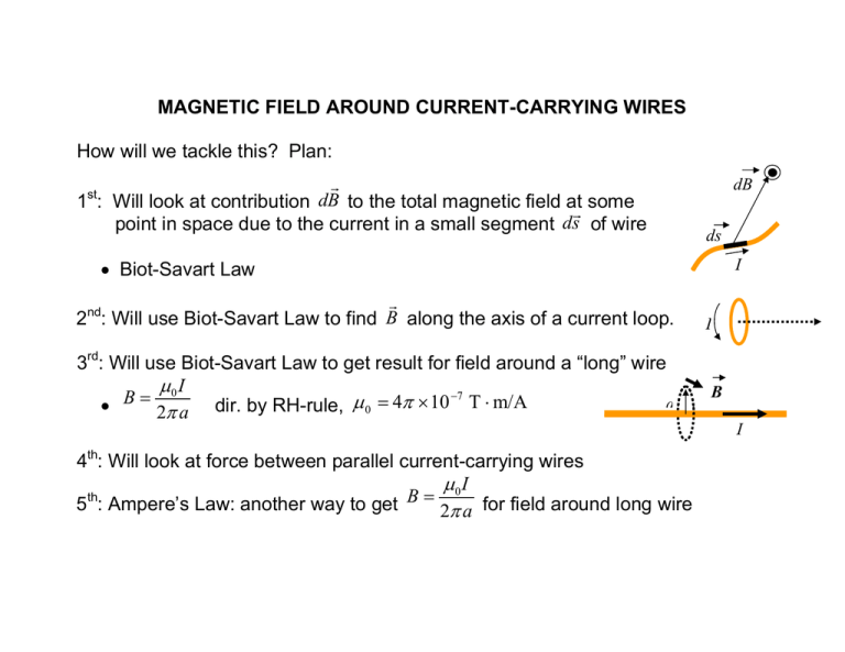
MAGNETIC FIELD AROUND CURRENT-CARRYING WIRES How will we tackle this? Plan: r 1 : Will look at contribution dB to the total magnetic field atr some point in space due to the current in a small segment ds of wire dB st ds I • Biot-Savart Law r 2 : Will use Biot-Savart Law to find B along the axis of a current loop. nd 3rd: Will use Biot-Savart Law to get result for field around a “long” wire µ0 I −7 B = µ = 4 π × 10 T ⋅ m/A a • dir. by RH-rule, 0 2π a 4th: Will look at force between parallel current-carrying wires µ0 I th B = 5 : Ampere’s Law: another way to get 2π a for field around long wire I B I P BIOT-SAVART LAW (22.7) r field at Expression for contribution dB to magnetic r P due to current I in small segment ds of wire r r I θ r • r̂ is UNIT VECTOR pointing ds → P ds r d s • r is DISTANCE from →P r • θ is the ANGLE between ds and r̂ r r Then contribution to B at P from ds is r µ 0 I dsr × rˆ dB = 4π r 2 −7 • µ 0 = 4π × 10 T ⋅ m/A is the permittivity of free space r r d s × rˆ (can also use RH-rule with thumb → current) d B • Direction of is from r µ 0 I dsr × rˆ BIOT-SAVART LAW: understanding dB = 4π r 2 r • For drawing, direction of d s × rˆ is out of screen/page P r r ds → r̂ ; thumb shows direction o Fingers sweep r d s × rˆ of r r d B • So at P due to ds points out of screen/page r θ ds r d s × rˆ = ds sin θ • Magnitude r r dB from ds are maximum for points on o For a given r, contributions r d s plane perpendicular to r r r o Current in ds makes NO contribution to dB at points along direction ds • For TOTAL FIELD at P, must sum (integrate) contributions from all segments of wire (don’t panic. We will only do special cases) I EXAMPLE: 22.6 in text – Magnetic field on axis of circular current loop Look at a loop of radius r located in the yz plane carrying a current I. What is the magnetic field a distance x from the centre of the loop along its axis? y ds dB θ r R R θ dB x x z r ds P I MAGNETIC FIELD AROUND A LONG (INFINITE) WIRE r r Biot-Savart Law gives contribution dB at P due to current I in segment ds r µ 0 I dsr × rˆ • dB = 4π r 2 dB P r r r o dB points out of screen/page at P by RH-rule ds r To get B at P due to WHOLE wire, must sum contributions from all angles r • Angle between ds and r̂ changes with position along wire! o Will state result and then sketch derivation I MAGNETIC FIELD AROUND A LONG (INFINITE) WIRE • Result of using Biot-Savart Law: r o Magnetic field lines circle wire → no component of B parallel to wire B I Iout r B • Magnitude of inversely proportional to perpendicular a distance from wire r µ0 I B= 2π a (IMPORTANT RESULT) • Direction of magnetic field lines: r B o Another Right-Hand Rule: thumb along I ; fingers curl in direction of r µ0 I “Sketch” of how we get B = 2π a from the Biot-Savart Law r Looking for B at a point P located perpendicular distance a from wire • Start with contribution to field at P due to r segment ds located distance s along the wire from the point closest to P : r µ 0 I dsr × rˆ dB = 4π r 2 r r d s × rˆ = ds sin θ o Note that ds × rˆ points out of the screen/page and that r r To get total B at P from infinite wire, could sum dB from s = −∞ to s = +∞ . r • Helps to express r and ds in terms of angle θ between ds and r̂ and then sum from θ = 0 to θ = π r µ0 I “Sketch” of how we get B = 2π a from the Biot-Savart Law (continued) Changing Variables: a a r = = sin θ • From r get sin θ a = − tan θ s = −a cot θ • Tricky point: for θ as shown, s is negative so that s or • Use derivative to relate ds to dθ ds a 2 = a csc θ = o From dθ sin 2 θ we get ds = a dθ sin 2 θ r µ0 I “Sketch” of how we get B = 2π a from the Biot-Savart Law (continued) Doing the integral. So far, we have: a r = • sin θ a dθ ds = • sin 2 θ so r a dθ ds × rˆ = ds sin θ = sin θ r So contribution to field at P from ds is r µ I ds × rˆ µ 0 I dB = 0 = sin θ dθ 4π r 2 4π a µ0 I π µ0 I = = − B sin θ d θ cos θ Magnitude of total field is: 4π a ∫0 4π a RESULT: field at distance a from wire with current I: π = 0 µ0 I 2π a B= µ0 I 2π a µ0 I = B USE 2π a TO FIND MAGNETIC FORCE BETWEEN PARALLEL WIRES I1 a B2 F1 B2 a I2 µ0 I 2 B = • Field at I1 due to I2 is 2 2π a o Exerts a force on length l of I1: I1 r r r F1 = I 1l × B2 µ 0 l I1 I 2 F I lB = = o Magnitude of force on length l of I1 is 1 1 2 2π a F1 I2 MAGNETIC FORCE BETWEEN PARALLEL WIRES F1 µ0 I1 I 2 • Force on I1 per unit length is l = 2π a toward I2 (for currents in same dir.) By Newton’s 3rd law, F2 µ 0 I1 I 2 • Force on I2 per unit length is l = 2π a toward I1 (for currents in same dir.) In general: • For parallel conductors, current in same direction: F µ 0 I1 I 2 o Wires ATTRACT with force per unit length l = 2π a • For parallel conductors, current in opposite direction: F µ 0 I1 I 2 o Wires REPEL with force per unit length l = 2π a Provides definition of AMPERE: −7 • For 2 wires, 1 m apart, I 1 = I 2 = 1 A → force per unit length is 2 × 10 N/m


