damping improvement through tuning controller limits of a
advertisement
DAMPING IMPROVEMENT THROUGH TUNING
CONTROLLER LIMITS OF A SERIES FACTS DEVICE
Jung-Wook Park* and Ian A. Hiskens**
* Core Technology Group, LG Electronics Inc., Seoul, South Korea
** Department of Electrical and Computer Engineering, University of Wisconsin-Madison, USA
(Emails: jungwookpark@ieee.org and hiskens@engr.wisc.edu)
ABSTRACT
The external controller (EC) of a series flexible ac transmission
system (FACTS) device, which is the series capacitive reactance
compensator (SCRC), can provide effective damping of lowfrequency oscillations in a power system. The saturation limiter
in the EC is used to enforce practical limits resulting from the
system restriction such as equipment and component ratings. In
this paper, the effect of saturation limits on the overall system
dynamic behavior is analyzed. Also, a systematic nonlinear
tuning method is proposed to determine the optimal values for
saturation limits.
In this paper, the new contribution is made by analyzing the
effects of the saturation limiter (with non-smooth nonlinearities)
on system dynamics of a power network equipped with the
SCRC device. Also, the nonlinear optimization method is
proposed to determine the optimal values for saturation limits.
This paper is organized as follows: Section II presents a
summary of the SCRC and EC. The effect of the saturation
limiter on the system dynamic behavior is illustrated in Section
III. The optimal tuning method for the saturation limits is
described in Section IV. Finally, the conclusions are given in
Section V.
2. SCRC - SERIES FACTS DEVICE
1. INTRODUCTION
Rapid progress in power electronics has opened up new
opportunities to control power and/or voltages, and this can be
used to increase the capacities of existing power lines. In the last
decade, the series flexible ac transmission systems (FACTS)
devices have been progressively developed to deal with the
above control objectives [1].
Among many power-electronic-based controllers that influence
power flow in power lines, the controllable series capacitive
reactance compensator (SCRC) using a voltage-source pulsewidth-modulated (PWM) inverter has attracted attention for its
rapid response control capability to not only control the steady
state, but also provide damping during disturbances [2]-[3].
Damping is also improved by applying external controller (EC)
to the SCRC with the aid of properly designed supplementary
controls [4].
The control outputs from the EC with high gains can cause
undesirable response in a physical system. To enforce practical
limits resulting from the system restriction, the saturation limiter
following the EC is used. The overall power system structure,
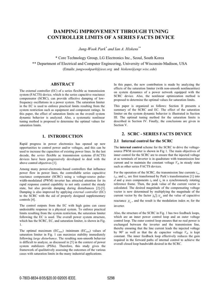
which has the SCRC, EC, and saturation limiter, is shown in Fig.
1.
The optimal maximum (ECmax) /minimum (ECmin) values of
saturation limiter in Fig. 1 can maximize stability immediately
following large disturbance. The resulting non-smooth behavior
is difficult to analyze, as discussed in [5] in the context of power
system stabilizers (PSSs). Therefore, this study gives the
framework of qualitatively assessing the outcomes of the various
cases with saturation limits in the many industrial applications.
0-7803-8834-8/05/$20.00 ©2005 IEEE.
2.1 Internal control for the SCRC
The internal control scheme for the SCRC to drive the voltagesource PWM inverter is shown in Fig 1. The main objectives of
inner control for the SCRC are to ensure that the injected voltage
at ac terminals of inverter is in quadrature with transmission line
current and to maintain the constant voltage Vdc in steady state
such as other series FACTS devices.
For the operation of the SCRC, the transmission line currents isa,
isb, and isc are first transformed by Park’s transformation [1] into
d and q axes components id and iq in a synchronously rotating
reference frame. Then, the peak value of the current vector is
calculated. The desired magnitude of the compensating voltage
vector is now determined by multiplying the magnitude of the
current vector by the factor 2 2 /Vdc and the value of capacitive
reactance X C , and the result is the modulation index mi for the
inverter.
Also, the structure of the SCRC in Fig. 1 has two feedback loops,
which are an inner power control loop and an outer voltage
control loop. The outer control loop ensures that no real power is
exchanged between the inverter and the transmission line,
thereby ensuring that the line current leads the injected voltage
by 90q as well as that the dc capacitor voltage Vdc is kept
constant. The inner feedback loop effectively reduces the gain
required in the forward paths of internal control to achieve the
overall closed loop bandwidth desired in the SCRC.
5298
{T
n
sGJX
sGJY
X
X
Y
Y
z
Gn
h}yGT
l
X C*
+
6
'Z
1
1 sTC
1
1 sTC
m
'w
1
1 sTC
1
1 sTC
m
K C sT W
1 sT W
kG
j
Kp
kG
n
ECmin
+
s
6
'j
6
}Q
6
X2
H}
-
KP
wQ +
-
6
+
H
pUG
w
T
HT
wTs
GsG
OwssP
lG
j
X
wGVGh
j wpG
w
2 2
Vdc
X
XC
+
+
w
z G
G
SGSG
ECmax
KP T
KI
s
}G
z
w~tGp
D
+
+
6
}
KF
zjyj
Kv
Figure 1. External controller (EC) and saturation limiter for the SCRC in a power system.
The advantage gained by the inclusion of the inner feedback loop
is, therefore, that the necessary bandwidth of the phase-locked
loop can be achieved with less compromise in the response of the
system to a disturbance on the dc side of the inverter.
More details for the internal control of the SCRC are given in [3]
and [4].
2.2 External control for the SCRC
The objective of the external controller (EC) for the SCRC
(dashed block in Fig. 1) is to improve the system damping
performance with the properly chosen external variables. It is
suggested in [4] that the speed deviation signal ' Z and active
power deviation signal ' PS (which exhibits the derivative
behavior of the ' Z ) from a generator could be used to generate
the supplementary control signal 'X C for the EC located close
3. EFFECT OF SATURATION LIMITS ON
SYSTEM DYNAMICS
The effect on the damping performance of the saturation limits is
evaluated by a 100 ms three-phase short circuit applied at the
infinite bus at 1 sec. The generator operates with a rotor angle of
16.38q (Pt = 0.25 pu, Qt = 0.16 pu) at a pre-fault steady state
operating point, where the same amount of power is flowing in
Line #1 and Line #2 (with the same line impedances).
The simulation results are given in Figs. 2 to 4. It is clearly
shown from Figs. 2 and 3 that the EC improves damping
performance compared to the system without the EC. The
corresponding EC output response ('XC [pu]) with non-smooth
nonlinear dynamics due to saturation limits is shown in Fig. 4.
to that generator. Further explanation for the EC design is given
in [4].
without EC
EC with saturation limits [0.05 -0.05]
EC with saturation limits [0.1 -0.1]
30
To design controller that satisfies the constraints of physical
systems, the saturation limiter following the EC is now
considered with non-smooth nonlinear dynamic behavior being
the focus in this paper.
Rotor angle [Degree]
25
2.3 Example system description
The power system in Fig.1 consists of the single generator (160
MVA, 15 kV (L-L)) connected to an infinite bus through two
transmission lines, labeled Line #1 and Line #2. The parameters
of the synchronous generator are given in [6]. The EXAC1A
(IEEE type alternator supplied rectifier excitation systems) and
H_TUR1/GOV1 (IEEE type hydro turbine-governor) models in
PSCAD/EMTDC library [7] are used as the AVR/exciter and
turbine/governor systems, respectively.
20
15
10
5
0
1
2
3
4
Time [s]
5
6
Figure 2. Rotor angle response (G [q]).
5299
7
8
state values of Z and PS, respectively. Minimization is achieved
through variation of the saturation limits O=[ECmax ECmin].
2
without EC
EC with saturation limits [0.05 -0.05]
EC with saturation limits [0.1 -0.1]
1.5
4.2 Computation of gradients
Speed deviation [rad/s]
1
Minimization of the nonlinear J in (1) requires knowledge of
derivatives. Parameters O explicitly describe a non-smooth
influence on behavior in a system that already involves switching
devices of the voltage-source PWM inverter. Therefore, it is
impossible to analytically determine the derivative of J with
respect to parameters O. However it has been shown in [8]-[9]
that the required gradients, also known as trajectory sensitivities,
are well defined for non-smooth, nonlinear systems. Furthermore,
they can be efficiently computed as a by-product of numerical
integration of the nominal trajectory.
0.5
0
-0.5
-1
-1.5
0
1
2
3
4
Time [s]
5
6
7
8
Figure 3. Speed deviation response ('Z [rad/s]).
0.1
EC with saturation limits [0.05 -0.05]
EC with saturation limits [0.1 -0.1]
0.08
0.06
0.04
' XC [pu]
0.02
0
Given the availability of gradient information, many numerical
optimization methods based on the first-order gradients can be
applied to minimize the function J in (1). The steepest descent
method, which is the simplest first-order numerical optimization
algorithm, is used to implement in this paper. The cost function
in (1) has the form of a continuous-time nonlinear least-squares
problem. A corresponding continuous-time adaptation of the
Gauss-Newton or Broyden-Fletcher-Goldfarb-Shanno (BFGS)
algorithms [10] is also appropriate, and can be efficiently
applied.
4.3 Results
-0.02
The damping performance achieved by the optimal saturation
limits (which are [0.0559 –0.0971] for [ECmax ECmin]) is
compared with that of the initial output limits ([0.05 –0.05] and
[0.1 –0.1]) by a 100 ms three-phase short circuit applied at the
infinite bus in Fig. 1 at 1 sec.
-0.04
-0.06
-0.08
-0.1
0
1
2
3
4
Time [s]
5
6
7
8
Figure 4. EC output response ('XC [pu]): supplementary
controls for the SCRC.
4. OPTIMAL TUNING OF LIMTER
4.1 Optimization for non-smooth controller
In multivariable nonlinear problems, numerical optimization
methods play significant role in finding optimal solutions and
selecting parameters by which the objective function J can be
minimized/maximized. The optimal tuning problem for the
limiter described in this paper is of this form.
The speed deviation ('G) and active power deviation ('Ps) from
the generator, which are inputs of the EC, are considered good
indicators of the damping. Therefore, damping improvement is
equivalent to minimizing the objective function
J ( Ȝ)
³
tf
t0
T
§ª
¨ Z ( Ȝ, t ) Z * º
W
¨«
*»
¨ ¬« Ps ( Ȝ, t ) Ps ¼»
©
ª Z ( Ȝ, t ) Z * º ·¸
dt , «
*» ¸
¬« Ps ( Ȝ, t ) Ps ¼» ¸¹
where W is the diagonal matrix of weighting factors and tf is an
appropriate final time. The Z* and PS* are the post-fault steady
The ECmax value of 0.0559 has changed little from the initial
positive limit value 0.05, but ECmin has moved from –0.05 to –
0.0971, which is close to –0.1. The corresponding result is shown
in Fig. 5. Note that the negative limit ECmin is effective to damp
the first swing, and the positive limit ECmax improves damping
performance after first swing (see the second swing).
Also, the values of the cost function J are compared in Table 1.
The variations of the cost function J optimized during the 5
iterations are shown in Fig. 6.
5. CONCLUSION
This paper made the new contribution by applying the nonlinear
optimization algorithm to tune the saturation limiter used in the
external controller (EC) for the series capacitive reactance
compensator (SCRC), which is a series flexible ac transmission
system (FACTS) device. Trajectory sensitivities provided the
derivatives of an objective function with respect to parameters
that related directly to the non-smoothness of the limiter. The
optimal limit values determined by the proposed method
improved the overall system damping performance.
The systematic approach proposed in this paper to optimally tune
the limiter can give a framework for industrial applications with
saturation limits that affect the overall system dynamics.
5300
30
28
E C w it h s at ura tion lim it s [ 0. 1 -0 .1]
26
E C w it h s at ura tion lim it s [ 0. 05 -0.0 5]
Rotor angle [Degree]
24
E C w it h s at ura tion lim it s
[0. 055 9 -0 .09 71] by op tim al t unin g
22
20
18
16
14
12
10
8
0
1
2
3
4
Tim e [s ]
5
6
7
8
Figure 5. Rotor angle response (G [q]).
0.18
[2]
0.16
Value of J
0.14
[3]
0.12
0.1
0.08
[4]
0.06
0.04
0
1
2
3
4
5
Iterations
Figure 6. Values of the cost function J variations.
[5]
Table 1: Comparisons of the cost function J
[ECmax ECmin]
Cost, J
[0.05
-0.05]
0.1716
[0.1
-0.1]
0.0847
[0.0559 –0.0971]
[6]
[7]
[8]
0.0594
[9]
6. REFERENCES
[1] N.G. Hingorani and L. Gyugyi, “Understanding FACTSConcepts and Technology of Flexible AC Transmission
[10]
5301
Systems,” IEEE Press, New York, 2000, ISBN 0-78033455-8.
X. Wang, S.-Z. Dai, and B. T. Ooi, “A series capacitive
reactance compensator based on voltage source PWM
converter,” in Conf. Rec. IEEE-IAS Annual Meeting,
pp.918-924, 1991.
Bruce S. Rigby and R.G. Harley, “An Improved control
Scheme for a Series-Capacitive Reactance Compensator
Based on a Voltage-Source Inverter,” IEEE Trans. on
Industry Applications, Vol.34, No.2, pp. 355-363,
March/April 1998.
Jung-Wook Park, R.G. Harley, and G.K. Venayagamoorthy,
“New External Neuro-Controller for Series Capacitive
Reactance Compensator in a Power Network,” IEEE Trans.
on Power Systems, Vol.19, No.3, pp. 1462-1472, August
2004.
Ian A. Hiskens, “Systematic Tuning of Nonlinear Power
System Controllers”, in Proc. of IEEE International
Conference on Control Applications, pp.19-24, September
2002.
P.M. Anderson and A.A. Fouad, “Power system control and
stability,” IEEE Press, New York, 1994.
Manitoba HVDC Research Centre Inc: “Introduction to
PSCAD/EMTDC Version 4.2”.
Ian A. Hiskens and M.A. Pai, “Trajectory sensitivity
analysis of hybrid systems,” IEEE Trans. on Circuits and
Systems I, Vol.47, No.2, pp. 204-220, February 2000.
Ian A. Hiskens, “Power system modeling for inverse
problems,” IEEE Trans. on Circuits and Systems I: Regular
Papers, Vol.51, No.3, pp. 539-551, March 2004.
J. Nocedal and S. J. Wright, Numerical Optimization,
Springer-Verlag, New York, 1999.
