SOLENOID AND PRESSURE-OPERATED VALVE TECHNOLOGY
Proportional solenoid valves
ASCO Posiflow® Valves
ASCO markets a range of proportional solenoid valves under
the registered trade name Posiflow®.
1 - Proportional action
Most flow control valves work on an “on/off” basis. They are
either fully open or fully closed. Proportional valves, however,
operate with a “proportional” action. By varying the electrical
input to a proportional valve, the flow of the fluid through the
valve can be continuously and steplessly adjusted between
0 to 100% of the maximum rated flow.
00009GB-2016/R01
Availability, design and specifications are subject to change without notice. All rights reserved.
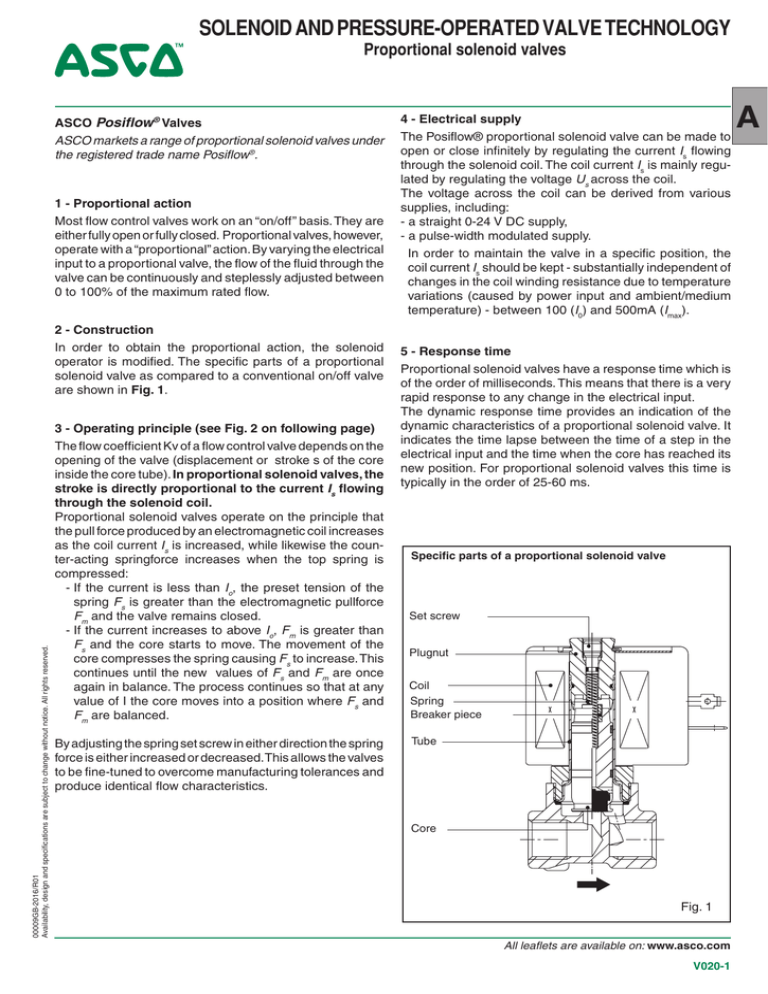
2 - Construction
In order to obtain the proportional action, the solenoid
operator is modified. The specific parts of a proportional
solenoid valve as compared to a conventional on/off valve
are shown in Fig. 1.
3 - Operating principle (see Fig. 2 on following page)
The flow coefficient Kv of a flow control valve depends on the
opening of the valve (displacement or stroke s of the core
inside the core tube). In proportional solenoid valves, the
stroke is directly proportional to the current Is flowing
through the solenoid coil.
Proportional solenoid valves operate on the principle that
the pull force produced by an electromagnetic coil increases
as the coil current Is is increased, while likewise the counter-acting springforce increases when the top spring is
compressed:
- If the current is less than Io, the preset tension of the
spring Fs is greater than the electromagnetic pullforce
Fm and the valve remains closed.
- If the current increases to above Io, Fm is greater than
Fs and the core starts to move. The movement of the
core compresses the spring causing Fs to increase. This
continues until the new values of Fs and Fm are once
again in balance. The process continues so that at any
value of I the core moves into a position where Fs and
Fm are balanced.
By adjusting the spring set screw in either direction the spring
force is either increased or decreased.This allows the valves
to be fine-tuned to overcome manufacturing tolerances and
produce identical flow characteristics.
4 - Electrical supply
The Posiflow® proportional solenoid valve can be made to
open or close infinitely by regulating the current Is flowing
through the solenoid coil. The coil current Is is mainly regulated by regulating the voltage Us across the coil.
The voltage across the coil can be derived from various
supplies, including:
- a straight 0-24 V DC supply,
- a pulse-width modulated supply.
In order to maintain the valve in a specific position, the
coil current Is should be kept - substantially independent of
changes in the coil winding resistance due to temperature
variations (caused by power input and ambient/medium
temperature) - between 100 (I0) and 500mA (Imax).
5 - Response time
Proportional solenoid valves have a response time which is
of the order of milliseconds. This means that there is a very
rapid response to any change in the electrical input.
The dynamic response time provides an indication of the
dynamic characteristics of a proportional solenoid valve. It
indicates the time lapse between the time of a step in the
electrical input and the time when the core has reached its
new position. For proportional solenoid valves this time is
typically in the order of 25‑60 ms.
Specific parts of a proportional solenoid valve
Set screw
Plugnut
Coil
Spring
Breaker piece
Tube
Core
Fig. 1
All leaflets are available on: www.asco.com
V020-1
A
Proportional solenoid valves - SOLENOID AND PRESSURE-OPERATED VALVE TECHNOLOGY
Linearity
Flow curves usually show a curvature at both its “bottom”
and “top” ends, in between which there is the “lineair”working
part of the curve. The “(non‑)linearity” is the degree to which
the actual flow curve deviates from an ideal straight line
(expressed as a percentage within a specified linear region
of the curve).
Hysteresis
This is the difference in the flow rate at the same value of
the electrical input, depending on whether this set value was
reached from “below”, i.e. increasing the electrical input, or
from “above” i.e. while decreasing the electrical input.
The hysteresis is expressed as a percentage of the maximum flow rate.
Threshold
The electrical input necessary to cause a significant flow
rate from the zero position. The threshold is expressed as
a percentage of the maximum electrical input value.
Sensitivity
The change in electrical input necessary to produce a noticeable change in the flow rate when the valve is moved from
a stationary position in the same direction as the original
direction. The sensitivity is expressed as a percentage of
the maximum electrical input value.
Reverse sensitivity
The change in electrical input necessary to produce a
noticeable change in the flow rate when the valve is driven
from a stationary position in a direction opposite to the
original direction.
The reverse sensitivity is expressed as a percentage of the
maximum electrical input value.
3
2
Q
max
Flow (Q)
6
The previous mentioned flow regulation characteristics are
closely related. They are caused by a number of factors, in
order of importance:
- the electromagnetic signal conversion (electromagnetic
hysteresis),
- the friction between the moving and static components
of the valve,
- the play in the mechanical interaction between the core
and the valve seat, and
-
variations in the pressure differential (∆P) across the
valve.
Repeatability
The spread in the flow rates is called the repeatability.
7 - Features of a proportional solenoid valve
-C
losed loop control systems - The possibility of controlling the valves by means of electrical inputs from sensors
allows them to be used in the range of applications with
closed loop control systems for fluid control.
- Safety features - In the case of a power failure or if the
electrical input is interrupted the valves close immediately
- in many cases an important safety consideration.
- Long life, low maintenance - Proportional solenoid operators have only a single moving part, the core, guided by
two high-precision, glass-filled PTFE guide rings.
8 - Electronic control unit (Fig. 3)
The ASCO electronic control unit provides a convenient way
of operating the Posiflow® valve. It accepts all the standard
control signals from the sensors/transmitters used in modern control systems. The coil voltage supply is regulated
by means of pulse-width modulation. An important built-in
feature is a function which keeps the current through the
coil (at a specific control signal) constant, independent of
changes in the coil winding resistance or variations in the
supply voltage.
The pulse-width is determined by the control signal Ui (Ii)
(either a voltage or a current).
Various control signals can be selected:
. 0 - 10 V DC
. 4 - 20 mA
. 0 - 20 mA
1
4
7
24
5
0
Is
0
I0
I max
Electrical input (I)
Fig. 2
Reverse sensitivity
Increasing coil current
5
Linear flow region
6
3
Decreasing coil current
7
Sensitivity
4
Hysteresis
8
Threshold
1
2
All leaflets are available on: www.asco.com
V020-2
Flow linearity
Voltage
8
U (V)
I/F
Ugem 6V
1
2
24
0
Ugem 12V
1
2
24
0
Ugem 18V
1
2
24
Ugem 24V
0
1
2
t (m/sec)
Coil current (~ magnetic force)
Fig. 3
00009GB-2016/R01
Availability, design and specifications are subject to change without notice. All rights reserved.
6 - Flow regulation characteristics (Fig. 2)
The performance of a valve is specified in a number of
properties:


