RF-RR
Date of Issue: 06/03/2013
Issue Number: 5.0
Page 1 of 4
RF-RR
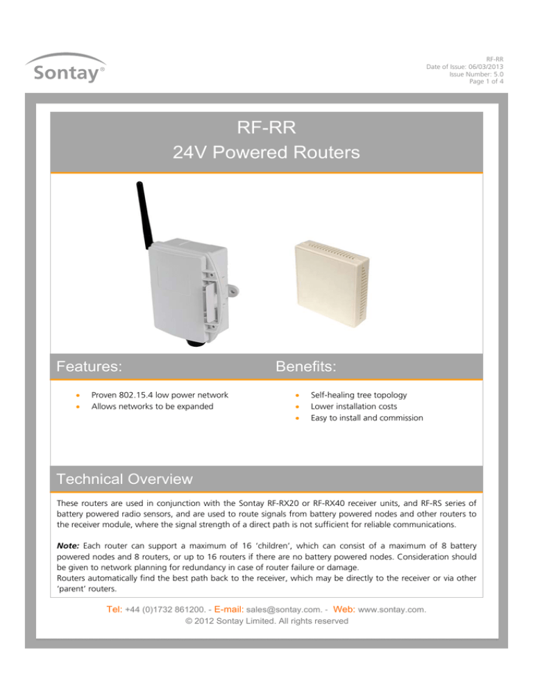
24V Powered Routers
Features:
Benefits:
Proven 802.15.4 low power network
Allows networks to be expanded
Self-healing tree topology
Lower installation costs
Easy to install and commission
Technical Overview
These routers are used in conjunction with the Sontay RF-RX20 or RF-RX40 receiver units, and RF-RS series of
battery powered radio sensors, and are used to route signals from battery powered nodes and other routers to
the receiver module, where the signal strength of a direct path is not sufficient for reliable communications.
Note: Each router can support a maximum of 16 ‘children’, which can consist of a maximum of 8 battery
powered nodes and 8 routers, or up to 16 routers if there are no battery powered nodes. Consideration should
be given to network planning for redundancy in case of router failure or damage.
Routers automatically find the best path back to the receiver, which may be directly to the receiver or via other
‘parent’ routers.
Tel: +44 (0)1732 861200. - E-mail: sales@sontay.com. - Web: www.sontay.com.
© 2012 Sontay Limited. All rights reserved
RF-RR
Date of Issue: 06/03/2013
Issue Number: 5.0
Page 2 of 4
Specification:
Part Codes:
Common specification:
Radio Output:
Frequency
2.4GHz
16 channels, automatically selected
Direct-sequence spread spectrum
Compliance
IEEE 802.15.4-2006
Data Encryption
AES 128
Power Output
+10dBm
Power Supply
24Vac/dc
Operating:
Temperature
-10 to +50°C
RH
0 to 90%, non-condensing
Country of origin
UK
RF-RR-600
Plant housing router
Plant Housing:
Material
Dimensions
Protection:
Snap-shut lid
Aerial Characteristics:
Gain
VSWR
Space Housing:
Material
Dimensions
Protection
Aerial Characteristics:
Gain
VSWR
RF-RR-T-900
Space housing router
ABS (flame retardant type VO)
116 x 106 x 52mm
IP54
IP65 (see page 4 note 8)
2.0dBi
<2:1
ABS (flame retardant)
85 x 85 x 23mm
IP30
1.2dBi
1.5:1
The products referred to in this data sheet meet the
requirements of EU Directive 2004/108/E
Tel: +44 (0)1732 861200. - E-mail: sales@sontay.com. - Web: www.sontay.com.
© 2012 Sontay Limited. All rights reserved
RF-RR
Date of Issue: 06/03/2013
Issue Number: 5.0
Page 3 of 4
How It Works:
Routers are used to route signals from battery powered nodes and other routers to the receiver module, where the signal
strength of a direct path is not sufficient for reliable communications.
Data is transmitted back to the receiver at configurable time intervals, or on a configurable change in measured value. Each
sensor retains these configurations if the battery becomes discharged or requires replacement.
The routers and receiver automatically select which of the 16 transmission channels available gives the best radio network
performance, taking into account both signal strength and interference levels from adjacent channels and equipment (such
as Wi-Fi etc.) The routers automatically find the best path back to the receiver, which may be directly to the receiver or via
“parent” routers.
NB Each router can support a maximum of 16 “children”, a maximum of 8 of which can be battery powered “end devices”
and a maximum of which can be 8 routers. Consideration should be given on network planning for redundancy in case of
router failure or damage.
Aerial Orientation (plant sensor types);
For best results ensure that the main body of the aerial is vertical.
Installation:
Plant Sensor types:
1.
Remove all packaging from the sensor.
2.
Note the MAC address printed on the affixed label and note where this MAC address is installed.
3.
Mount the sensor in the required position (this will have been determined by the site survey tool, (see the quick
start guide and manual).
4.
It is recommended that the unit be mounted with the cable entry at the bottom. If the cable is fed from above then
into the cable gland at the bottom, it is recommended that a rain loop be placed in the cable before entry into the
sensor.
Tel: +44 (0)1732 861200. - E-mail: sales@sontay.com. - Web: www.sontay.com.
© 2012 Sontay Limited. All rights reserved
RF-RR
Date of Issue: 06/03/2013
Issue Number: 5.0
Page 4 of 4
Installation (continued):
5.
Release the snap-fit lid by gently squeezing the locking tab and feed the cable through the waterproof gland &
terminate the cores at the terminal block. Leaving some slack inside the unit, tighten the cable gland onto the cable
to ensure water tightness.
6.
Observe correct polarity if using a 24Vdc power supply. To power on the unit, fit J200.
7.
Snap shut the lid after the connections have been made if IP65 protection is required, secure the lid with two
screws provided.
8.
Ensure, at a minimum, that all routers and the receiver on the radio network are powered on, and allow about 5
minutes for the network to auto-commission before attempting to read values or make configuration changes.
Space Sensor Types:
1.
Remove all packaging from the sensor.
2.
Note the MAC address printed on the affixed label and note where this MAC address is installed.
3.
Mount the sensor in the required position (this will have been determined by the site survey tool, (see the quick
start guide and manual).
4.
Undo the tamperproof screw at the bottom of the housing and gently pull the front panel from the base.
5.
Using the base as a template mark the hole centres and fix to the wall with suitable screws. Alternatively the base
plate can be mounted on to a conduit box or a standard recessed back box.
6.
Feed cable through the 22mm knockout in the base of the housing and terminate the cores at the terminal block as
required. Leaving some slack inside the unit.
7.
Observe correct polarity if using a 24Vdc power supply. To power on the unit, fit J200.
8.
Replace the housing to the base plate.
9.
Re-fit the tamperproof screw through the lug at the bottom of the base plate.
10. Ensure, at a minimum, that all routers and the receiver on the radio network are powered on, and allow about 5
minutes for the network to auto-commission before attempting to read values or make configuration changes.
Whilst every effort has been made to ensure the accuracy of this specification, Sontay cannot accept responsibility for damage, injury,
loss or expense from errors or omissions. In the interest of technical improvement, this specification may be altered without notice.
Tel: +44 (0)1732 861200. - E-mail: sales@sontay.com. - Web: www.sontay.com.
© 2012 Sontay Limited. All rights reserved


