Metallographic Specimen Preparation Basics
advertisement
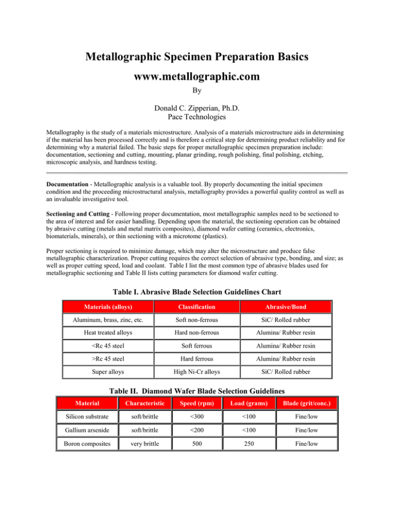
Metallographic Specimen Preparation Basics www.metallographic.com By Donald C. Zipperian, Ph.D. Pace Technologies Metallography is the study of a materials microstructure. Analysis of a materials microstructure aids in determining if the material has been processed correctly and is therefore a critical step for determining product reliability and for determining why a material failed. The basic steps for proper metallographic specimen preparation include: documentation, sectioning and cutting, mounting, planar grinding, rough polishing, final polishing, etching, microscopic analysis, and hardness testing. Documentation - Metallographic analysis is a valuable tool. By properly documenting the initial specimen condition and the proceeding microstructural analysis, metallography provides a powerful quality control as well as an invaluable investigative tool. Sectioning and Cutting - Following proper documentation, most metallographic samples need to be sectioned to the area of interest and for easier handling. Depending upon the material, the sectioning operation can be obtained by abrasive cutting (metals and metal matrix composites), diamond wafer cutting (ceramics, electronics, biomaterials, minerals), or thin sectioning with a microtome (plastics). Proper sectioning is required to minimize damage, which may alter the microstructure and produce false metallographic characterization. Proper cutting requires the correct selection of abrasive type, bonding, and size; as well as proper cutting speed, load and coolant. Table I list the most common type of abrasive blades used for metallographic sectioning and Table II lists cutting parameters for diamond wafer cutting. Table I. Abrasive Blade Selection Guidelines Chart Materials (alloys) Classification Abrasive/Bond Aluminum, brass, zinc, etc. Soft non-ferrous SiC/ Rolled rubber Heat treated alloys Hard non-ferrous Alumina/ Rubber resin <Rc 45 steel Soft ferrous Alumina/ Rubber resin >Rc 45 steel Hard ferrous Alumina/ Rubber resin Super alloys High Ni-Cr alloys SiC/ Rolled rubber Table II. Diamond Wafer Blade Selection Guidelines Material Characteristic Speed (rpm) Load (grams) Blade (grit/conc.) Silicon substrate soft/brittle <300 <100 Fine/low Gallium arsenide soft/brittle <200 <100 Fine/low Boron composites very brittle 500 250 Fine/low Ceramic fiber composites very brittle 1000 500 Fine/low Glasses brittle 1000 500 Fine/low Minerals friable/brittle >1500 >500 Fine/low Alumina ceramic hard/tough >1500 >500 Medium / low Zirconia (PSZ) hard/tough >3500 >800 Medium/low Silicon nitride hard/tough >3500 >800 Medium/low Metal matrix composites - >3500 >500 Medium/high General purpose - variable Variable Medium/high Mounting - The mounting operation accomplishes three important functions (1) it protects the specimen edge and maintains the integrity of a materials surface features (2) fills voids in porous materials and (3) improves handling of irregular shaped samples, especially for automated specimen preparation. The majority of metallographic specimen mounting is done by encapsulating the specimen into a compression mounting compound (thermosets - phenolics, epoxies, diallyl phthalates or thermoplastics - acrylics), casting into ambient castable mounting resins (acrylic resins, epoxy resins, and polyester resins), and gluing with a thermoplastic glues. Compression mounting - For metals, compression mounting is widely used. Phenolics are popular because they are low cost, whereas the diallyl phthalates and epoxy resins find applications where edge retention and harder mounts are required. The acrylic compression mounting compounds are used because they have excellent clarity. Table IIIa and IIIb list the application as well as the physical properties of the most common compression mounting resins. Table IIIa. Compression Mounting Application Properties Cost Ease of use Availability of colors Cycle times Edge retention Clarity Hardness Phenolics Acrylics Low Excellent Moderate Moderate Epoxy (glass filled) Moderate Good Yes No No No Excellent Fair None Low Moderate Good Excellent Good Good Excellent None High Good Excellent None High Diallyl Phthalates Moderate Good Table IIIb. Compression Mounting Resin Physical Properties Resin Phenolic Acrylic Epoxy Diallyl Phthalate Form Granular Powder Granular Granular Specific gravity (gm/cm3) 1.4 0.95 1.75-2.05 1.7-1.9 Colors Black, Red, Green Clear Black Blue Shrinkage (compression)(in/in) 0.006 - 0.001-0.003 0.001-0.003 Coefficient of Linear Thermal Expansion (in/in/°C 10-6) 50 - 28 19 Chemical resistance Glycol, petrochemicals, solvents, some acids and bases Alcohol, dilute acids & alkalies, and oxidizers Solvents, acids, alkalies Solvents, acids, alkalies 143°-177°C (290°-350°F) 17-28 MPA (2500-4000 psi) 160°-177°C (320°-350°F) 24-41 MPA (3500-6000 psi) Molding temperature Molding pressure 150°-165°C (300°-330°F) 21-28 MPa (3050-4000 psi) - Hardness - Rockwell M63 Barcol 72 - Curing time (1/2" mount @ temp.) and pressure) 90-120 seconds 2-4 minutes 90-120 seconds 90-120 seconds Castable mounting resins are commonly used for electronic and ceramic materials. Castable mounting resins are recommended for brittle and porous materials. These mounting compounds are typically two component systems (1resin and 1-hardener). Typical curing times range from minutes to hours with the faster curing resins producing higher exothermic temperature which causes the mounting material to shrink away from the edge during curing. For example, the Acrylic Cold Mounting Resins cure in less than 10 minutes and Epoxy Castable Resins cure in approximately 4-6 hours. Note that adding an external energy source such as heat or microwave energy can enhance the Epoxy Castable Resin curing cycle. It is recommended that the room temperature be less than 85° F to avoid overheating and uncontrollable curing of the mounting compound. Table IV lists the basic properties of castable mounting resins. Table IV. Castable Mounting Resin Properties Type Peak Temperature Shore D Hardness Cure Time Comments EPOXY Epoxy resin and hardener ACRYLIC POLYCAST Resin Acrylic resin and powder Polyester resin and hardener 82° F 80° F 100° F 82 80 76 6-8 hours Moderate hardness, low shrinkage, transparent 5-8 minutes Very fast curt, translucent, some shrinkage 6-8 hours Transparent, clear Planar Grinding - or course grinding is required to planarize the specimen and to reduce the damage created by sectioning. The planar grinding step is accomplished by decreasing the abrasive grit/ particle size sequentially to obtain surface finishes that are ready for polishing. Care must be taken to avoid being too abrasive in this step, and actually creating greater specimen damage than produced during cutting (this is especially true for very brittle materials such as silicon). The machine parameters, which effect the preparation of metallographic specimens, include grinding/polishing pressure, relative velocity distribution, and the direction of grinding/polishing. Grinding Pressure Grinding/polishing pressure is dependent upon the applied force (pounds or Newton's) and the area of the specimen and mounting material. Pressure is defined as the Force/Area (psi, N/m2 or Pa). For specimens significantly harder than the mounting compound, pressure is better defined as the force divided by the specimen surface area. Thus, for larger hard specimens higher grinding/polishing pressures increase stock removal rates, however higher pressure also increases the amount of surface and subsurface damage. Note that for SiC grinding papers, as the abrasive grains dull and cut rates decrease, increasing grinding pressures can extend the life of the SiC paper. Higher grinding/polishing pressures can also generate additional frictional heat, which may actually be beneficial for the chemical mechanical polishing (CMP) of ceramics, minerals and composites. Likewise for extremely friable specimens such as nodular cast iron, higher pressures and lower relative velocity distributions can aid in retaining inclusions and secondary phases. Relative Velocity Current grinding/polishing machines are designed with the specimens mounted in a disk holder and machined on a disk platen surface. This disk on disk rotation allows for a variable velocity distribution depending upon the head speed relative to the base speed (Table V). Table V. Recommended Grinding/Polishing Speeds Head Speed (rpm) Base Speed (rpm) Relative Velocity Distribution 150 300 to 600 High 150 150 Minimal Characteristic Application • • Aggressive stock removal Differential grinding across the specimen surface • Useful for gross removal on hard specimens • Matching head and base speed in the same direction eliminates relative velocity distributions Uniform stock removal Low stock removal Produces minimal damage • Provides superior flatness over the specimen Useful for retaining inclusions and brittle phases • • • • For high stock removal, a slower head speed relative to a higher base speed produces the most aggressive grinding/ polishing operation. The drawback to high velocity distributions is that the abrasive (especially SiC papers) may not breakdown uniformly, this can result in non-uniform removal across the specimen surface. Another disadvantage is that the high velocity distributions can create substantially more specimen damage, especially in brittle phases. In all cases, it is not recommended to have the head rotating contra direction to the base because of the non-uniform removal and abrasive breakdown that occurs. Minimal relative velocity distributions can be obtained by rotating the head specimen disk at the same rpm and same direction as the base platen. This condition is best for retaining inclusions and brittle phases as well as for obtaining a uniform finish across the entire specimen. The disadvantage to low relative velocity distributions is that stock removal rates can be quite low. In practice, a combination of a high velocity distribution (150 rpm head speed/ 300 - 600 rpm base speed) for the initial planarization or stock removal step, followed by a moderate speed and low velocity distribution (120-150 rpm head speed/ 150 rpm base speed) step is recommended for producing relatively flat specimens. For final polishing under chemical mechanical polishing (CMP) conditions where frictional heat can enhance the chemical process, high speeds and high relative velocity distributions can be useful as long as brittle phases are not present (e.g. monolithic ceramics such as silicon nitride and alumina). Grinding Direction The orientation of the specimen can have a significant impact on the preparation results, especially for specimens with coatings. In general, when grinding and polishing materials with coatings the brittle component should be kept in compression. In other words, for brittle coatings the direction of the abrasive should be through the coating and into the substrate. Conversely, for brittle substrates with ductile coatings, the direction of the abrasive should be through the brittle substrate into the ductile coating. Manual Preparation - In order to insure that the previous rough grinding damage is removed when grinding by hand, the specimen should be rotated 90 degrees and continually ground until all the scratches from the previous grinding direction are removed. If necessary the abrasive paper can be replace with a newer paper to increase cutting rates. Automated Preparation - The key to successful automated preparation is to thoroughly clean the specimens between each abrasive grit size that is used. The tracking of the specimens should also uniformly break down the SiC paper, otherwise non-uniform grinding will occur (especially for hard specimens in soft mounts). In other words, the specimen should track across the entire diameter of the SiC paper. Abrasive Selection - The most common abrasive used for planar grinding metal and polymer metallographic specimens is silicon carbide (SiC). Silicon carbide is an excellent abrasive for planar grinding because it is very hard and maintains a sharp cutting edge as it breaks down during cutting. SiC abrasives are typically listed by the grit size. Table VI shows the two most common grit size-numbering systems, along with their respective median diameter particle size and Table VII provides a list of recommendation for planar grinding specific materials. Table VI. Particle Size vs. Common Grit Sizes for Abrasive Papers GRIT NUMBER European Standard grit (P-grade) 60 60 80 80 100 100 120 120 150 150 180 180 220 220 P240 240 P280 P320 280 P360 320 P400 P500 360 P600 400 P800 P1000 500 P1200 600 P2400 800 P4000 1200 Median Diameter, (microns) 250 180 150 106 90 75 63 58.5 52.2 46.2 40.5 35 30.2 25.75 21.8 18.3 15.3 6.5 2.5 Figure 1. SEM micrograph of 600 grit SiC Abrasive Paper (original mag. 150x) Table VII. Planar Grinding Recommendations Metallic Specimens For metallic specimen grinding, sequential grinding with silicon carbide (SiC) abrasive paper is the most efficient and economical rough grinding process. Although extremely coarse grit abrasive papers can be found, it is recommended that a properly cut specimen not be rough ground with an abrasive greater than 120 grit SiC paper. A typical abrasive grinding procedure would consist of 120 or 240 grit SiC paper followed by decreasing the size of the SiC paper (320, 400, and 600 grit). Finer papers are also available for continued abrasive paper grinding (800 and 1200 grit). In addition to the correct sequence and abrasive size selection, the grinding parameters such as grinding direction, load and speed can affect the specimen flatness and the Electronic Specimens Plasma Spray Components Ceramics and Ceramics Composites Plastics and Plastics Composites depth of damage. The basic idea is to remove all of the previous specimen damage before continuing to the next step while maintaining planar specimens. Grinding electronic components is very dependent upon both the substrate (silicon, alumina, barium titanate, plastic PCB's, etc) and the metallic materials used. In general, when grinding plated or coated materials, it is recommended that the coating be prepared in compression to prevent the coating from separating from the substrate. Silicon specimens should be have been sectioned with a fine grit diamond blade and cut as near as possible to the area of interest. For rough grinding, fine abrasives such as 400 or 600 grit SiC or a 15-micron diamond lapping film is recommended to avoid producing more damage than created during sectioning. Hard ceramic substrates (especially porous materials) should be rough polished with diamond lapping films to minimize edge rounding and relief between the widely varying materials hardness'. Similar to the preparation of electronic components, plasma spray coatings should be kept in compression to minimize the possibility of delamination at the coating/ substrate interface. For ceramic plasma spray coatings, diamond-lapping films are recommended to minimize edge rounding or relief and to maintain the integrity of any inclusions within the coating. Rough grinding ceramics and ceramic matrix composites should be performed with 15 or 30 micron diamond on a metal mesh cloth in order to obtain adequate stock removal and to minimize surface and subsurface damage. Plastics are generally very soft and therefore can be planar ground with sequentially decreasing SiC abrasive paper grit sizes. When plastics are used in conjunction with hard ceramics, planar grinding can be very tricky. For these composite materials cutting must minimize damage as much as possible because almost all grinding and polishing will cause relief between the soft plastic and the hard ceramic. Following proper cutting, grinding with as small as possible a diamond (6-micron diamond) on a metal steel mesh cloth or the use of lapping films is suggested. Rough Polishing - The purpose of the rough polishing step is to remove the damage produced during cutting and planar grinding. Proper rough polishing will maintain specimen flatness and retain all inclusions or secondary phases. By eliminating the previous damage and maintaining the microstructural integrity of the specimen at this step, a minimal amount of time should be required to remove the cosmetic damage at the final polishing step. Rough polishing is accomplished primarily with diamond abrasives ranging from 9 micron down to 1-micron diamond. Polycrystalline diamond because of its multiple and small cutting edges, produces high cut rates with minimal surface damage, therefore it is the recommended diamond abrasive for metallographic rough polishing on low napped polishing cloths. Table VIII lists the basic rough polishing guidelines for a number of materials. Table VIII. Basic Rough Polishing Guidelines Metals (ferrous, nonferrous, tool steels, ys, etc.) Ceramics and ceramic matrix composites (CMC) Polymer matrix composites (PMC) Biomaterials Microelectronic Rough polishing typically requires two polishing steps, such as a 6-micron diamond followed by a 1-micron diamond on low napped polishing cloths. Low nap-polishing pads using polycrystalline diamond alternating with colloidal silica. This provides a chemical mechanical polishing (CMP) effect, which results in a damage free surface finish. Diamond lapping films Low napped polishing pads with polycrystalline diamond alternating with colloidal silica. Alternatively, diamond lapping films may work well Diamond lapping films specimens Plastics and polymers Plasma spray materials 800 and 1200 grit SiC abrasive paper Diamond lapping films or low napped polishing pads with alternating diamond and colloidal silica abrasives Final Polishing - The purpose of final polishing is to remove only surface damage. It should not be used to remove any damage remaining from cutting and planar grinding. If the damage from these steps is not complete, the rough polishing step should be repeated or continued (Table IX). Table X describes the most common polishing pads for metallographic specimen preparation. Table IX. Recommended Final Polishing Guidelines Metals (ferrous, nonferrous, tool steels, ys, etc.) Ceramics and ceramic matrix composites (CMC) Polymer matrix composites (PMC) Biomaterials High napped polishing pads with a colloidal alumina polishing abrasive. The polishing times should nominally be less than 30 seconds. Low napped polishing pads using 1 um polycrystalline diamond alternating with colloidal silica or colloidal silica alone. Fine abrasive diamond lapping films followed by a very light polish on a high napped polishing pad. Low napped polishing pads with polycrystalline diamond, alternating with colloidal silica. Alternatively, diamond lapping films may work well Microelectronic specimens Plastics and polymers Plasma spray materials Diamond lapping films followed by a very light polish on a high napped polishing pad Light polish with alumina on a high napped polishing pad Diamond lapping films followed by a very light and short alumina or colloidal silica polish on a high napped polishing pad Table X. Polishing Cloth Selection Guideline Metal Mesh cloth - this is a wire mesh material useful for coarse and intermediate lapping/polishing. The texture of this wire allows for the abrasive to become semi-fixed; thus offering the advantage of increased stock removal, while minimizing damage. Polyester Polishing Pads - synthetic polyester polishing pads have a similar action to a nylon pad, with the exception that it is much more durable. It is used in the intermediate polishing steps Pellon Pads - These are the most commonly used low napped polishing cloth material for the intermediate polishing steps. It is also a commonly used final polishing pad for ceramics. Porometric Polymer Pads - have a consistency similar to a rubber type of polishing pad. These types of low nap pads behave as an intermediate polishing pad with a performance between low napped and high napped pads Nylon Polishing Cloths - are high napped final polishing pad for most metals and polymers. Its high nap provides it a very soft and gentle polishing action High Napped Polishing Pads - are the most common final polishing cloths for metals and polymers. Its high nap provides it a very soft and gentle polishing action. Etching - The purpose of etching is to optically enhance microstructural features such as grain size and phase features. Etching selectively alters these microstructural features based on composition, stress, or crystal structure. The most common technique for etching is selective chemical etching and numerous formulations have been used over the years. Other techniques such as molten salt, electrolytic, thermal and plasma etching have also found specialized applications. Chemical etching selectively attacks specific microstructural features. It generally consists of a mixture of acids or bases with oxidizing or reducing agents. For more technical information on selective chemical etching consult corrosion books which discuss the relationship between pH and Eh (oxidation/reduction potentials), often known as Eh-pH diagrams or Pourbaix diagrams. Over the years numerous chemical etchants have been formulated. Some of the more common chemical etchants are listed in the following table. Table XI lists some of the more common etchants. Table XI. Common Chemical Etchants CAUTION: Safety is very important when etching. Be sure to wear the appropriate protective clothing and observe all WARNINGS on chemical manufacturers MSDS. Also review COMMENTS Section for each etchant. Etchant Kellers Etch Kroll's Reagent Composition 190 ml Distilled water 5 ml Nitric acid 3 ml Hydrochloric acid 2 ml Hydrofluoric acid 92 ml Distilled water 6 ml Nitric acid 2 ml Hydrofluoric acid Application Conditions Aluminum alloys 10-30 second immersion. Use only fresh etchant Titanium 15 seconds Comments Nital 100 ml Ethanol 1-10 ml Nitric acid Carbon steels, tin, and nickel alloys Seconds to minutes Kallings Reagent 40 ml Distilled water 2 grams Copper chloride (CuCl2) 40 ml Hydrochloric acid 40-80 ml Ethanol (85%) or Methanol (95%) Wrought stainless steel, Fe-Ni-Cr alloys Immerse or swab for few seconds to a few minutes Lepito's Reagent 50 ml Acetic acid 50 ml Nitric acid High temperature steels Swab Marble's Reagent 50 ml Distilled Water 50 ml Hydrochloric acid 10 grams Copper sulfate Stainless steels, Nickel alloys Immersion or swab etching for a few seconds Murakami Reagent 100 ml Distilled Water 10 grams K3Fe(CN)8 10 grams NaOH or KOH Wrought Stainless steel, tungsten alloys, silver alloys, SiC, B4C Immerse or swab for seconds to minutes Use fresh Picral 100 ml Ethanol 2-4 grams Picric acid Iron and steel, tin alloys Seconds to minutes Do not let etchant crystallize or dry explosive Vilella's Reagent 45 ml Glycerol 15 ml Nitric acid 30 ml Hydrochloric acid Stainless steel, carbon steel, cast iron Seconds to minutes Electrolytic etching is another fairly common etching technique. It is similar to chemical etching in that acids and bases are used for modifying the pH, however the electrochemical potential is controlled electrically by varying the voltage and current externally as opposed to chemically. Electrolytic etching is often used for harder to etch specimens that do not respond well to basic chemical etching techniques. Electrolytic techniques require that the specimen be conductive and are therefore limited primarily to metals. The most common electrolytic etching equipment uses a two-electrode design (anode and cathode) with acids or bases for the electrolyte. Procedures for this type of electrolytic etching are fairly common and can be found in the literature. Another type of electrolytic etching requires more sophisticated electrochemical equipment (potentiostats). This equipment uses a three-electrode configuration (anode, cathode, and reference) which allows the current and voltage to be adjusted independent of each other. In comparison to the two-electrode system, voltage is altered with the electrolyte dictating the current conditions. On the other hand, the electrolyte for the three-electrode configuration only requires a conductive solution such as KCl, instead of highly corrosive acids or bases. Molten Salt etching is a combination of thermal and chemical etching techniques. Molten salt etching is useful for grain size analysis for hard to etch materials such as ceramics. The technique takes advantage of the higher internal energy associated at a materials grain boundaries. At the elevated temperature of molten salts, the higher energy at the grain boundaries is relieved, producing a rounded grain boundary edge, which can be observed by optical, or electron microscope techniques. Thermal etching is a useful etching technique for ceramic materials. Thermal etching is technique that relieves the higher energy associated at the grain boundaries of a material. By heating the ceramic material to temperatures below the sintering temperature of the material and holding for a period of minutes to hours the grain boundaries will seek a level of lower energy. The result is that the grain boundary edge will become rounded so that it can be evaluated by optical or electron microscope techniques. Depending upon the ceramic material, the atmospheric condition of the furnace may need to be controlled. For example, etching silicon nitride will require either a vacuum or an inert atmosphere of nitrogen or argon to prevent oxidation of the surface to silicon dioxide. Plasma etching is a lesser-known technique that has been used to enhance the phase structure of high strength ceramics such as silicon nitride. For silicon nitride, the plasma is a high temperature fluoride gas, which reacts with the silicon nitride surface producing a silicon fluoride gas. This etching technique reveals the intragrain microstructure of silicon nitride. Metallographic Analysis Metallurgical analysis (metallography) of the microstructural provides the Material Scientist or Metallurgist information varying from phase structure, grain size, solidification structure, casting voids, etc. Figure 2 shows an example of two cast iron structures. Figure 2a shows a cast iron microstructure which has graphite flakes. Over time this materials will most likely fail under load. On the other hand by adding some solidifying agents the cast iron can be made to form the more durable graphite nodules (Figure 2b). Figure 3 shows the grain size of a tough pitch copper. Analysis of a materials grain size provides valuable information regarding a materials physical hardness and ductility. Microstructural analysis can also provide very useful information about the types of phases that occur during cooling. Figure 4 shows the dendritic growth of the microstructure for an aluminum-silicon alloy which formed during solidification. The direction and size of these dendrites again relate to the materials strength and durability. Other examples of metallographic analysis include: analyzing printed circuit board (PCB) solder hole connections, microelectronic failure analysis, steel heat treating such as surface hardening, ceramic grain size and porosity, polymer composite fiber wetting and orientation, etc. Figure 2. Cast Iron microstructures (a) graphite flakes (b) nodules Figure 3. Tough Pitch Copper microstructure showing grain size Figure 4. Aluminum-silicon alloy solidification microstructure Microscopic Analysis Bright Field (B.F.) illumination is the most common illumination technique for metallographic analysis. The light path for B.F. illumination is from the source, through the objective, reflected off the surface and returning through the objective and back to the eyepiece or camera. This type of illumination produces a bright background for flat surfaces with the non-flat features (pores, edges, etched grain boundaries) being darker as light is reflected back at an angle. Dark Field (D.F.) illumination is a lesser know illumination but powerful illumination technique. The light path for D.F. illumination is from the source, down the outside of the objective, reflected off the surface and returning through the objective and back to the eyepiece or camera. This type of illumination produces a dark background for flat surfaces with the non-flat features (pores, edges, etched grain boundaries) being brighter as light is reflected at an angle back into the objective. Differential Interference Contract (DIC) - is a very useful illumination technique for providing enhanced specimen features. DIC uses a normarski prism along with a polarizer in the 90° crossed positions. The two light beams are made to coincide at the focal plane of the objective, thus rendering height differences visible as variations in color. Optical Interferometry - is a technique that provides precise details of a materials surface topography. The simplest interferometer employs the interference between two beams of light. One beam is focused on the specimen and the second beam on an optically flat reference surface. The two reflected beams are then recombined by the beam splitter and pass through the eyepiece together. The two beams reinforce each other for those points on the specimen for which their path lengths are either the same of differ by an integral multiple of the wavelength, nλ. The beams cancel for path differences of nλ /2. Today's interferometers provide quantitative 3-dimensional surface topography information. The two most common optical interferometry techniques include - phase shifting interferometry (PSI) which uses a PZT to shift the optical path of the objective and vertical scanning interferometry (VSI) which changes the focus range of the objective. The main differences between PSI and VSI are that PSI has a higher z-axis resolution, whereas VSI has a larger scan range. PSI and VSI can also be combined to provide both high surface resolution and a larger scan range. Atomic Force Microscopy (AFM) - Is a non-optical technique that provides angstrom level surface profiling information. AFM's are very powerful tools and can be provide electrochemical, magnetic, and other surface feature information. Hardness Testing Hardness Testing provides useful information, which can be correlated to tensile strength, wear resistance, ductility, and other physical characteristics. Hardness testing is therefore useful for monitoring quality control and for the materials selection process. Table XII compares the various hardness testing applications. Microhardness is primarily determined with Knoop and Vickers indenters under test loads in the range of 1 to 1000 gram-force and are used to measure the hardness of specific phases, small particles and brittle materials. • Knoop hardness number (HK) is determined based on the size that of a diamond indenter (rhombic-based, pyramidal diamond) produces under a known applied load. The HK number is calculated by dividing the applied load (kilogram-force) by the projected area of the indentation (square millimeters). • Vickers hardness number is obtained by dividing the applied load in kilogram-force by the surface area of the indentation. The area of the indentation produced from the Vickers square-based pyramidal diamond is determined by the mean distance between the two diagonals of the indentation. Rockwell hardness (HR) is an indentation hardness test that is determined with a spheroconical penetrator or hard steel ball that is forced into the specimen surface. The test is accomplished by bringing the specimen into contact with the penetrator, the penetrator is then slowly forced into the specimen surface by weights acting through a system of levers, and when the load is released a dial pointer indicates the hardness number. Table XII. Hardness Tester Characteristics Type Rockwell C Rockwell B Brinell Vickers Microhardness Penetrator Diamond cone 1/16 inch steel ball 10 mm steel ball Diamond pyramid Diamond pyramid General hardness range covered Medium to very hard Surface preparation before testing 100 Soft to medium Fine grinding 500-3000 Soft to hard Coarse grinding 5-100 Very soft to very hard Fine grinding 0.01-50 Very soft to very hard Fine polishing Typical range of loads, kg 150 Fine grinding Typical applications Production testing of finished parts Production testing of finished parts Production testing of unfinished parts Laboratory investigations Test of microconstituents of alloys and ceramics Summary Microstructural analysis is extremely important in today's world where metals, ceramics, polymers, and composites are used to improve our everyday lives by insuring safety and reliability in the products that we use. In order, to correctly analyze these microstructures, proper specimen preparation is required to eliminate preparation induced microstructural artifacts. By knowing the physical properties of the material such as hardness, recrystallization temperature, fracture toughness; an appropriate specimen preparation procedure can be developed. In general, minimizing the damage early in the microstructural preparation stage by choosing the correct abrasive, lubricant, and equipment parameters, the steps required to highlight the representative materials microstructure obtained by following the basic preparation guidelines outlined in this paper. References 1. Pace Technologies Educational Web page at http://www.metallographic.com/Basics.htm About the Author Dr. Donald Zipperian is the Vice President of Technology for Pace Technologies, which manufacturers both equipment and consumables for the metallographic and surface finishing fields. Dr. Zipperian has had many years of experience developing equipment and consumables for metallography, 3-dimensional metrology, and industrial surface finishing. He has served on the MTQC board for ASM, been a member of the ASTM E-4 committee on Metallography, chaired and presented at various technical seminars, and has published numerous papers on metallography and metrology analysis. Prior to joining Pace Technologies, Dr. Zipperian has worked for Veeco Metrology in Tucson, AZ; Seagate Magnetic Recording Heads in Minneapolis, MN; and for Buehler as both the General Manager of their AZ Research Center and as Manager of Long Term Planning and Development.
