Simulation of Sensorless Speed Control of Induction Motor
advertisement

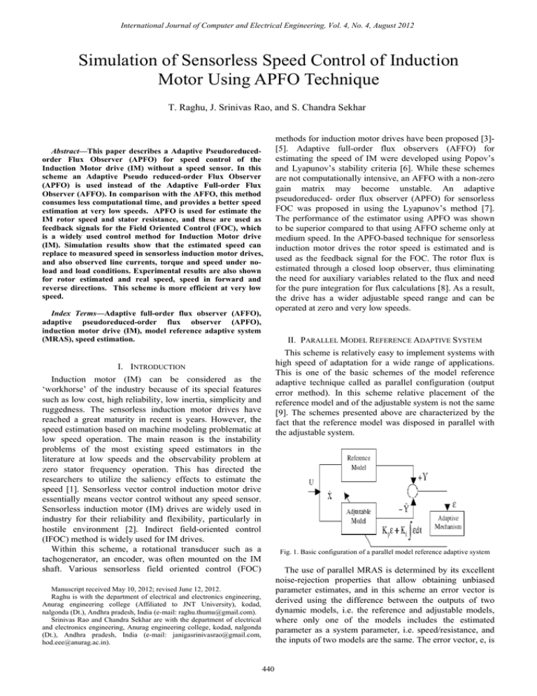
International Journal of Computer and Electrical Engineering, Vol. 4, No. 4, August 2012 Simulation of Sensorless Speed Control of Induction Motor Using APFO Technique T. Raghu, J. Srinivas Rao, and S. Chandra Sekhar Abstract—This paper describes a Adaptive Pseudoreducedorder Flux Observer (APFO) for speed control of the Induction Motor drive (IM) without a speed sensor. In this scheme an Adaptive Pseudo reduced-order Flux Observer (APFO) is used instead of the Adaptive Full-order Flux Observer (AFFO). In comparison with the AFFO, this method consumes less computational time, and provides a better speed estimation at very low speeds. APFO is used for estimate the IM rotor speed and stator resistance, and these are used as feedback signals for the Field Oriented Control (FOC), which is a widely used control method for Induction Motor drive (IM). Simulation results show that the estimated speed can replace to measured speed in sensorless induction motor drives, and also observed line currents, torque and speed under noload and load conditions. Experimental results are also shown for rotor estimated and real speed, speed in forward and reverse directions. This scheme is more efficient at very low speed. Index Terms—Adaptive full-order flux observer (AFFO), adaptive pseudoreduced-order flux observer (APFO), induction motor drive (IM), model reference adaptive system (MRAS), speed estimation. methods for induction motor drives have been proposed [3][5]. Adaptive full-order flux observers (AFFO) for estimating the speed of IM were developed using Popov’s and Lyapunov’s stability criteria [6]. While these schemes are not computationally intensive, an AFFO with a non-zero gain matrix may become unstable. An adaptive pseudoreduced- order flux observer (APFO) for sensorless FOC was proposed in using the Lyapunov’s method [7]. The performance of the estimator using APFO was shown to be superior compared to that using AFFO scheme only at medium speed. In the APFO-based technique for sensorless induction motor drives the rotor speed is estimated and is used as the feedback signal for the FOC. The rotor flux is estimated through a closed loop observer, thus eliminating the need for auxiliary variables related to the flux and need for the pure integration for flux calculations [8]. As a result, the drive has a wider adjustable speed range and can be operated at zero and very low speeds. II. PARALLEL MODEL REFERENCE ADAPTIVE SYSTEM This scheme is relatively easy to implement systems with high speed of adaptation for a wide range of applications. This is one of the basic schemes of the model reference adaptive technique called as parallel configuration (output error method). In this scheme relative placement of the reference model and of the adjustable system is not the same [9]. The schemes presented above are characterized by the fact that the reference model was disposed in parallel with the adjustable system. I. INTRODUCTION Induction motor (IM) can be considered as the ‘workhorse’ of the industry because of its special features such as low cost, high reliability, low inertia, simplicity and ruggedness. The sensorless induction motor drives have reached a great maturity in recent is years. However, the speed estimation based on machine modeling problematic at low speed operation. The main reason is the instability problems of the most existing speed estimators in the literature at low speeds and the observability problem at zero stator frequency operation. This has directed the researchers to utilize the saliency effects to estimate the speed [1]. Sensorless vector control induction motor drive essentially means vector control without any speed sensor. Sensorless induction motor (IM) drives are widely used in industry for their reliability and flexibility, particularly in hostile environment [2]. Indirect field-oriented control (IFOC) method is widely used for IM drives. Within this scheme, a rotational transducer such as a tachogenerator, an encoder, was often mounted on the IM shaft. Various sensorless field oriented control (FOC) Fig. 1. Basic configuration of a parallel model reference adaptive system The use of parallel MRAS is determined by its excellent noise-rejection properties that allow obtaining unbiased parameter estimates, and in this scheme an error vector is derived using the difference between the outputs of two dynamic models, i.e. the reference and adjustable models, where only one of the models includes the estimated parameter as a system parameter, i.e. speed/resistance, and the inputs of two models are the same. The error vector, e, is Manuscript received May 10, 2012; revised June 12, 2012. Raghu is with the department of electrical and electronics engineering, Anurag engineering college (Affiliated to JNT University), kodad, nalgonda (Dt.), Andhra pradesh, India (e-mail: raghu.thumu@gmail.com). Srinivas Rao and Chandra Sekhar are with the department of electrical and electronics engineering, Anurag engineering college, kodad, nalgonda (Dt.), Andhra pradesh, India (e-mail: janigasrinivasrao@gmail.com, hod.eee@anurag.ac.in). 440 International Journal of Computer and Electrical Engineering, Vol. 4, No. 4, August 2012 driven to zero through an adaptive law [9]. One of the most noted advantages of this type of adaptive system is its high speed of adaptation. The main drawback of this algorithm is its sensitivity to inaccuracies in the reference model, and difficulties of designing the adaptation mechanism block. The schematic diagram of control strategy of induction motor with sensorless control is shown in Fig 2. Sensor less control induction motor drive essentially means vector control without any speed sensor. The inherent coupling of motor is eliminated by controlling the motor by vector control, like in the case of as a separately excited motor. The inverter provides switching pulses for the control of the motor. The flux and speed estimators are used to estimate the flux and speed respectively. These signals then compared with reference values and controlled by using the PI controller. III. SENSORLESS CONTROL Speed sensorless estimation as its name implies, is the determination of speed signal from an IM drive system without using rotational sensors. It makes use the dynamic equations of the IM to estimate the rotor speed component for control purposes. Estimation is carried out using the terminal voltages and currents which are readily available using sensors. Sensor less vector control induction motor drive essentially means vector control without any speed sensor. An incremental shaft mounted speed encoder, usually an optical type is required for closed loop speed or position control in both vector control and scalar controlled drives. A speed signal is also required in indirect vector control in the whole speed range and in direct vector control for the low speed range, including the zero speed start up operation. Controlled induction motor drives without mechanical speed sensors at the motor shaft have the attractions of low cost and high reliability. Drives operating in hostile environments or in high speed drives speed sensors can’t be mounted. To replace the sensor the information on the rotor speed is extracted from measured stator voltages and currents at the motor terminals. IV. ADAPTIVE FLUX OBSERVER In open loop estimator, especially at low speeds, parameters variation has significant influence on the performance of the drive both at steady state and transient state. However, it is possible to improve the robustness against parameters mismatch and also signal noise by using closed loop observers. The proposed observer is explained below A. Luenberger Observer The scheme is based on the fact that one observer estimates the rotor flux and the speed are derived by the stator current error and the estimated rotor flux. In terms of classification, the scheme that adopts an observer could be also treated as MRAS, where the motor is considered as the reference model and the observer is considered as the adjustable model. The IM model in terms of state variables in stationary reference frame is given as follows: ⎡i ⎤ d ⎡ is ⎤ ⎡ A11 A12 ⎤ ⎡ is ⎤ ⎡B1 ⎤ + ⎢ ⎥ v̂s = A⎢ s ⎥ + Bvs ⎢ ⎥ = ⎢A ⎢ ⎥ ⎥ dt ⎣ψ r ⎦ ⎣ 21 A22 ⎦ ⎣ψ r ⎦ ⎣0 ⎦ ⎣ψ r ⎦ (1) ⎡i ⎤ i s = [C ]⎢ s ⎥ ⎣ψ r ⎦ (2) where A is the motor parameters matrix, B is the input is the state matrix; C is the output matrix, variables vector, and (stator voltage) is the command The stator current and the rotor flux are estimated by the full order Luenberger state Observer described by the following equation: Fig. 2. Basic block diagram of sensorless control of induction motor. (3) The motor speed can be estimated by: (4) ̂ and ̂ are the where current errors calculated as the difference between the measured and the estimated currents. The block diagram for Fig. 3. Luenberger based speed estimation structure. 441 International Journal of Computer and Electrical Engineering, Vol. 4, No. 4, August 2012 Luenberger observer is represented in Fig 3. The basic Luenberger observer is applicable to a linear, time-invariant deterministic system. ωr ⎛ = ς⎜k ⎝ + p ki ⎞ ⎟ s ⎠ (5) where ς = A − B = ψˆ drs ψ qrs −ψˆ qrs ψ drs V. ADAPTIVE SCHEME FOR SPEED ESTIMATION The speed can be calculated by the Model Referencing Adaptive System. The basic block diagram of MRAS speed estimation system is shown in Fig 4. The model reference approach (MRAS) makes use of redundancy of twomachine model of different structures that estimate the same state variables. Both models are referred to in the stationary reference frame. As the name implies it consists of two models namely reference model and adaptive model, where the output of a reference model is compared with the output of an adjustable or adaptive model until the errors between the two models vanish to zero. With the correct value of rotor speed, the fluxes determined from the two models should match. An adaptation algorithm with P-I control can be used to tune the speed value until the two flux values match. In steady state, s ^ s ζ=0, balancing the fluxes; in other words, ^ s s Ψdr = Ψ dr and Ψqr = Ψ qr . The MRAS in Fig. 3 can be interpreted as a vector Phase Locked Loop (PLL) in which the output flux vector from the reference model is the reference vector and the adjustable model is a vector phase shifter controlled by ωr. VI. RESULTS A. Simulation Results The simulation of sensorless speed control of Induction Motor is done by using MATLAB®/SIMULINK. The results for different cases are given below. Case-1: Under No-Load Reference speed = 100 rad/s Fig. 4. Basic block diagram of MRAS speed estimation Fig. 6. 3-φ Currents, speed, and torque for no-load reference speed of 100 rad/s Case-2: Set Point Change Fig. 5. Actual speed and estimated speed using MRAS in rad/s In designing the adaptation algorithm for the MRAS, it is important to take account of the overall stability of the system and to ensure that the estimated speed will converge to the desired value with satisfactory dynamic characteristics. Using Popov’s criteria estimated speed is derived as follows: Fig. 7. Rotor speed (actual and estimated) 442 International Journal of Computer and Electrical Engineering, Vol. 4, No. 4, August 2012 Fig. 11. Experimental results of forward-reverse operations Fig. 8. 3-φ Currents, rotor speed, and torque Case 3: Reversal of Speed VII. CONCLUSION Sensorless control of induction motor using AFPO technique has been proposed. Sensorless control gives the benefits of Vector control without using any shaft encoder. The principle of Sensorless control of induction motor is given elaborately. The mathematical model of the drive system has been developed and results have been simulated. Simulation results of Sensorless Control of induction motor using AFPO technique were carried out by using Matlab/Simulink. The simulation results of the proposed scheme have been presented. Speed reversal command is applied at t = 0.5 s from -100 rad/s to +100 rad/s ACKNOWLEDGMENT We are thankful to Dr.P.Rajeswar Reddy, chairman, Anurag Group of Institutions, for his kindly co-operation in providing us the required infrastructure and facilities. We are thankful to Dr.Akash.N.Patwari, Principal, Anurag Engineering College, Kodad, for his encouragement and guidance. We are thankful to the faculty members of electrical and electronics Department, Anurag Engineering College, for their continuous support and guidance. Fig. 9. 3-φ Currents, rotor speed, and torque B. Experimental Results Fig 9 and Fig 10 shows the experimental results with sampling period of 0.5 ms. The APFO is implemented on PC interfaced to LAB Windows/CVI. An Intel 80C 196KD microcontroller is used for protection purposes. Experimental data are acquired through a data acquisition board. The agreement between the estimated and measured values of rotor speed shows that the MRAS estimator works precisely at forward and reverse directions. Fig. 10 shows experimental results of the forward-reverse operations under no load condition. REFERENCES [1] [2] [3] [4] [5] [6] [7] [8] Fig. 10. Actual speed and estimated speed 443 E. Levi and M. Wang, “Impact of parameter variations on speed estimation in sensorless rotor flux oriented induction machines,” IEEE Proc. Of Power Electronics and Variable Speed Drives, no. 456, pp. 305-310, September 1998. H. M. Kojabadi and L. Chang, “Model reference adaptive system pseudoreduced order flux observer for very low speed and zero speed estimation in sensorless induction motor drives,” IEEE annual power electronics specialists conference, Australia, vol. 1, 2002. M. Cirrincione and M. Pucci, “An MRAS-based sensorless highperformance induction motor drive with a predictive adaptive model,” IEEE Trans. on Industrial Electronics, vol. 52, no. 5, pp. 532-551. C. Schauder, “Adaptive speed identification for vector control of induction motor without rotational transducers,” IEEE Trans. on Industrial Applications, vol. 28, no. 5, pp. 1054-1061, October 1992. G. F. Profumo, C. Illas, R. Magueranu, and P. Vranka, “A unitary approach to speed sensorless induction motor field oriented drives based on various model reference schemes,” IEEE/IAS Annual Meeting, pp. 1594-1599, 1996. J. Maes and J. A. Melkebeek, “speed-sensorless direct torque control of induction motor using an adaptive flux observer,” IEEE Trans.on Ind Appl, vol. 36, no.3, pp. 778-785, 2000 S. Tamai, “Speed sensorless vector control of induction motor with model reference adaptive system,” Int. Industry Applications Society, pp. 189-195, 1987. E. Levi, M. Wang, “Impact of parameter variations on speed estimation in sensorless rotor flux oriented induction machines,” International Journal of Computer and Electrical Engineering, Vol. 4, No. 4, August 2012 [9] IEEE Proc. Of Power Electronics and Variable Speed Drives, no. 456, pp. 305-310, 1998. Y. D. Landau, Adaptive control – “The model Reference Approach,” Marcel Dekker, New York, 1979. T. Raghu was born in 1979. He received his M.Tech (Power Electronics) degree in Electrical and Electronics Engineering from Jawaharlal Nehru Technological University, Hyderabad. Presently he is working as assistant professor in Anurag engineering college, Kodad. He is guiding both undergraduate and post graduate student projects. His area of interest includes Power Electronics and Drives. J. Srinivas Rao was born in 1981. He received his M.Tech (Power Electronics) degree in Electrical and Electronics Engineering from Jawaharlal Nehru Technological University, Hyderabad. Presently he is working as assistant professor in Anurag engineering college, Kodad. He is guiding both undergraduate and post graduate student projects. His area of interest includes Power Electronics and Drives. S. Chandra Sekhar was born in 1978. He received his M.Tech (High Voltage Engineering) degree in Electrical and Electronics Engineering from Jawaharlal Nehru Technological University, Kakinada. Presently he is working as associate professor in Anurag engineering college, Kodad. He is guiding both undergraduate and post graduate student projects. His area of interest includes High voltage transmission, Power Electronics and Drives. 444


