Quick Start Guide
Smart Battery Switch (SBS) HW Version 3
Product Safety Warnings
The Smart Battery Switch (SBS) is only intended to be used as an engineering demonstrator. It is not intended for extensive use or to be re-used in a product or system that is
sold to consumers.
The SBS is intended to be used by electrical engineers who are experts in the field of
high current design. If you are not qualified, seek the help of an expert before using the
demonstrator.
Questions about the SBS should be directed to Infineon Application Engineering.
The cable, cable lug, washer and nut used to connect to the bolt mounted onto the SBS
demonstrator’s circuit board must all be made of high current-capable metals which will
not experience a significant temperature rise while conducting the current.
Battery Camping compliant to IEC 60095-2_Ed.4 (2009)
The cable lug must be mounted directly to the bolt (torque 6Nm ±1Nm).
Keep the current below 1800 A. The time a current may be applied is limited by
the temperature rise.
Don‘t exceed 1 Joule of switching energy.
Switching to high currents or to high switch off energy may destroy the switch and
the test setup and end up in fire.
Content
Schematic
How to connect the SBS
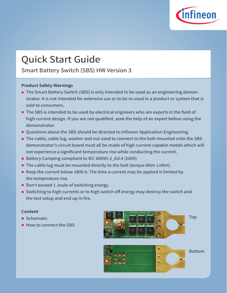
Top
Bottom
Schematic
Battery Positive
Terminal
Q1 … Q6
Drain
D5
IN414SW-13-F
R 1 … R6
100 Ω/150 V/1%
R21
1
IN2 10 kΩ/
2
150 V/1%
3
4
1
2
R22
3
TSW-103-08-G-S
10 kΩ/150 V/1%
InGND
R23
47 Ω/150 V/1%
Supply
Voltage max. = 18 V
IC2
8
VS
IN
7
DS
EN
6
G
ST
5
GND
SO
LTC1154CS8
Q10
BC807-25
g_ms
R9
1 kΩ/
150 V/
1%
D1
SZ1SMA5931BTB
C2
10 nF/
100 V/
XJR
R19
560 Ω/
150 V/
1%
D4
IN414SW-13-F
C3
10 nF/
100 V/
XJR
Gate
C4
220 nF/
50 V/
XJR
Q9
BC807-25
IN1
R8
10 kΩ/
150 V/
1%
D3
Voltage max.
15 V
R20
100 Ω/150 V/1%
R7
10 kΩ/
150 V/
1%
So
Designator
SmartBatterySwitch_Main_SW_V30.SchDoc
Output Terminal
Power
Clamp
ource
INT_VBB
R13
680 Ω/
150 V/
1%
R15
120 kΩ/
150 V/
1%
R14
120 kΩ/
150 V/
1%
120 kΩ/150 V/1%
5
3
4
C1
R18
R17
120 kΩ/
150 V/
1%
U1A
V+
V-
+IN
-IN
OUT
Q7
IPLU300N04S4-R7
2
1
LT6015IS5
Supply
Voltage max. = 50 V
R16
Q7 Active
Freewheeling
g_freewh
100 Ω/150 V/1%
Q8
IPLU300N04S4-R7
Q8 Wrong
Polarity
Protection
INT_GND
C1 = 100 nF/100 V/X7R
Battery Negative
Terminal
Schematic
Q1 … Q6 are in Parallel
Q1
R1
100 Ω/150 V/
1%
D3
P6SMB18CA
Q2
R3
100 Ω/150 V/
1%
Q3
Q4
R4
100 Ω/150 V/
1%
R5
100 Ω/150 V/
1%
Q5
R11
100 Ω/150 V/
1%
Q6
R12
100 Ω/150 V/
1%
Gate Protection/Voltage max. = 18 V
How to Connect the SBS
Battery Positive Terminal
Output Terminal
In1
InGND
In2
Battery
Negative
Terminal
IN1
IN2
Switch
N.C.
N.C.
On
L
N.C.
Off
N.C.
L
Off (latched)
N.C.
Reset latched
N.C.=Not connected
L =Connected to InGND
=Pull down In2 to InGND and
release again
Thermal Image after 10 minutes and 250A.
www.infineon.com/smart-battery-switch
www.infineon.com/mosfet
Order Number: DEMO_BATT_SW_V3
SP001332050
© 2015 Infineon Technologies AG. All Rights Reserved.


