cast resin transformers
advertisement

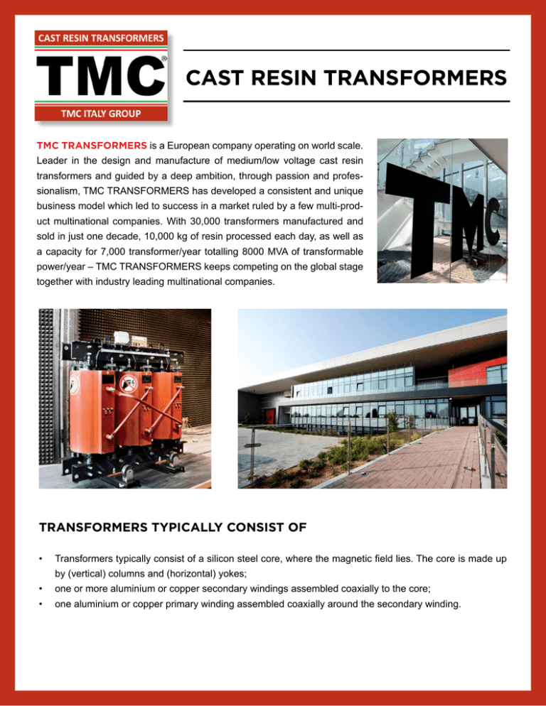
CAST RESIN TRANSFORMERS TMC TRANSFORMERS is a European company operating on world scale. Leader in the design and manufacture of medium/low voltage cast resin transformers and guided by a deep ambition, through passion and professionalism, TMC TRANSFORMERS has developed a consistent and unique business model which led to success in a market ruled by a few multi-product multinational companies. With 30,000 transformers manufactured and sold in just one decade, 10,000 kg of resin processed each day, as well as a capacity for 7,000 transformer/year totalling 8000 MVA of transformable power/year – TMC TRANSFORMERS keeps competing on the global stage together with industry leading multinational companies. TRANSFORMERS TYPICALLY CONSIST OF • Transformers typically consist of a silicon steel core, where the magnetic field lies. The core is made up by (vertical) columns and (horizontal) yokes; • one or more aluminium or copper secondary windings assembled coaxially to the core; • one aluminium or copper primary winding assembled coaxially around the secondary winding. THE CORE The magnetic core of TMC transformers is manufactured using magnetic grain-oriented silicon steel sheet. This type of steel is highly permeable by the magnetic field and its fluctuations, thus reducing losses. The joints between columns and yokes are Step-Lap inserted sheet, so that the magnetic stream flows more easily, SECONDARY WINDING The secondary winding (low voltage) is made up by an aluminum or copper single-plate conductor wound in an epoxy resin-soaked insulation on automatic winders which guarantee perfect tension and compactness of the coil. The wound coil is then vacuum-soaked. Thanks to the high-quality materials and the winding rigorous process, the coil optimizes heat dissipation and easily resists to electromechanical stress in case of short circuit. PRIMARY WINDING The primary winding (medium voltage) is made up by a thin aluminum or copper plate conductor wound together with a polyester insulating film. The winding consists of more coils continuously wound by computerized machines which also execute connections between the coils and the tap welds. Once completed, the winding is vacuum-insulated with quartz epoxy resins and then polymerized in a furnace. The process control ensures the highest mechanical homogeneousness of the winding. Great advantages are thus achieved in terms of resistance to thermal cycles, partial discharges and pollutants. • Highly resistant to fire and self-extinguishable; • Non-toxicity of combustion gases in case of fire; • The installation environment does not require particular characteristics (contrary to oil transformers which require fire or catchment barriers); • Use in highly humid and polluted environments; • Low installation costs; • No maintenance required (contrary to oil transformers); • Low losses during operation thanks to the possibility of installing transformers • In proximity of the load; • High resistance to short circuit stress; • High resistance to overvoltage; • High insulation degree and no partial discharges; • Smaller dimensions than dry-type non-cast resin transformers. APPLICATIONS LANDMARK PROJECTS The Shard Tower - London (UK) The Agabar Tower - Barcelona (Spain) Building Site – Fiera Milano City (Italy) Quirinale, Italian Presidential Palace - Rome AIRPORTS Malpensa Airport (Italy) Barcelona Airport (Spain) Yeravan International Airport (Armenia) Santorini Airport (Greece) RAILWAYS, METROWAY, TRAMWAY High speed train TGV (France) Angers Tramway (France) “Porta Nuova Garibaldi” Milan Railway Station (Italy) Wien Central Station (Austria) POWER PLANTS Nuclear Power Plant Olkiluoto (Finland) Scandale Power Plant (Italy) West Burton Power Plant (UK) Kyiv Hydroelectric Power Plant (Ukraine) Bachaquero & Tamare Power Plant (Venezuela) UNIVERSITIES AND HO SPITALS San Camillo Hospital Rome (Italy) Karolinska Univeristy Hospital (Sweden) J. Gutemberg University (Germany) PHOTOVOLTAIC POWER PLANTS Casella Photovoltaic Power Plant (Italy) Barcelona Photovoltaic Power Plant (Spain) Picaro Photovoltaic Power Plant (Italy) Ruvo Photovoltaic Power Plant (Italy) WIND FARMS Faro Farelo Wind Farm (Spain) Pehimo Wind Farm (Spain) Lucito (CB) and Melissa (KR) Wind Farms (Italy) Vallè du Moulin Wind Farm (France) TESTS ON TRANSFORMERS ARE REGULATED BY STANDARD IEC 60076-11 AND ARE DIVIDED INTO ROUTINE TESTS, TYPE TESTS AND SPECIAL TESTS STANDARD TESTS • measurement of the electrical resistance of windings; • K transformation ratio measurement and vector group check; • Ucc% short circuit voltage measurement; • Pcc short circuit losses measurement; • Po no-load losses and lo% no-load current measurement; • applied voltage insulation tests; • induced voltage insulation tests; • partial discharges measurement; • dimensions check. TYPE TESTS • lightning impulse test; • heating test. SPECIAL TESTS • noise level measurement; • short circuit resistance test; • thermal shock test (C1 – C2); • ambient test. Resistance thermometers are sensitive devices to temperature changes. The devices element is a thin platinum wire wound on a cast resin insulating support. The basic value of resistance is 100 ohm at 0° C with 0.1 ohm. Dielectric stiffness is 2,000 Vca. They are usually installed on every LV winding, and also on the core upon request. Additional resistance thermometers can be installed as reserves. The digital display control unit is usually installed on the MV board and has the following characteristics: • 3 or 4 input channels for platinum PT 100 ohm sensors; • configuration for the control of cooling fans; • 2 set-points with digital temperature pre-setting up to 220° C; • 18-270 Vcc-Vca supply; • carrying capacity of output contacts: 5 A; • absorbed power: 7 VA; • electrical protection (which does not fall within the scope of the monitoring system). Protection from other faults which may occur in or near the transformer is performed through the following devices. 68 69 HV SIDE (PRIMARY) HV feeder surge arrestor; HV line ground switch; overload dischargers; protection fuse-switch. LV SIDE ( SECONDARY) automatic protection switch. HV AND LV SIDE Protection against internal damage (differential protection), that can be performed through the differential relay. It is usually suggested for transformers above 1 MVA apparent power. During the normal operation of transformers, primary and secondary currents are proportionate to almost 1/k (inverse to the transformation ratio). If an anomalous current dissipation occurs due to failure, the ratio between the primary and secondary currents changes. The differential relay intervenes when the imbalance between the primary and secondary current exceeds the tolerable limit. TMC FACILITIES ITALY ASSEMBLING AND DISTRIBUTION FOR ASSEMBLY FACILITY CANADA


