Data Sheet pdf link
advertisement
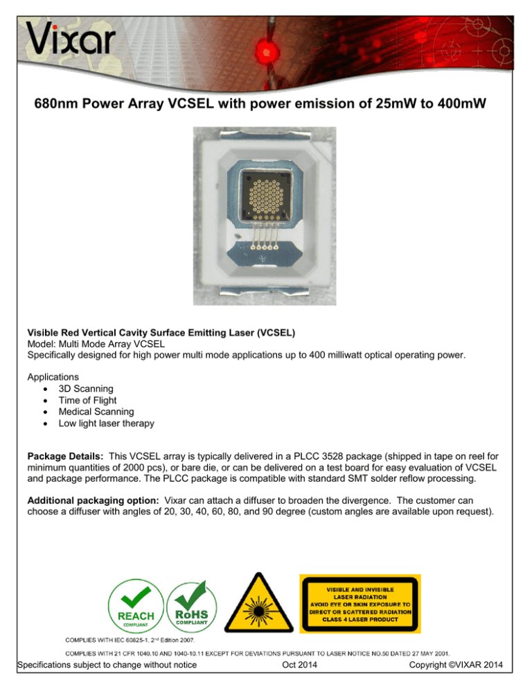
680nm Power Array VCSEL with power emission of 25mW to 400mW Visible Red Vertical Cavity Surface Emitting Laser (VCSEL) Model: Multi Mode Array VCSEL Specifically designed for high power multi mode applications up to 400 milliwatt optical operating power. Applications 3D Scanning Time of Flight Medical Scanning Low light laser therapy Package Details: This VCSEL array is typically delivered in a PLCC 3528 package (shipped in tape on reel for minimum quantities of 2000 pcs), or bare die, or can be delivered on a test board for easy evaluation of VCSEL and package performance. The PLCC package is compatible with standard SMT solder reflow processing. Additional packaging option: Vixar can attach a diffuser to broaden the divergence. The customer can choose a diffuser with angles of 20, 30, 40, 60, 80, and 90 degree (custom angles are available upon request). Specifications subject to change without notice Oct 2014 Copyright ©VIXAR 2014 Page 2 of 5 Absolute Maximum Ratings Parameter Storage temperature Operating temperature (VCSEL) Maximum package SMT solder reflow temperature CW current (VCSEL) Rating -40 to 100 °C -20 to 60 °C 250°C, 10 seconds 800 mA Maximum pulsed current 1.2 A Notes (Note 1) 20µs pulse width, 1% duty cycle, T=25°C (Note 2) Note 1: The maximum CW laser current in the Absolute Maximum Ratings is valid for the operating temperature noted at the top of this table; however, the maximum CW laser current decreases with increasing temperature. Contact Vixar for maximum CW laser current values at other temperatures. Note 2: For details refer to the Vixar Application Note "Operation of VCSELs Under Pulsed Conditions". (http://www.vixarinc.com/technology/applicationnotes.html) Stresses beyond those listed under Absolute Maximum Ratings may cause permanent damage to the device. These are stress ratings only. Functional operation of the device at these or any other conditions beyond those indicated for extended periods of time may affect device reliability. CW Typical Electro-Optical Characteristics VCSEL Operating Temp (Tv) =25°C Product ID Parameter Symbol Threshold current Ith Operating voltage Vf Optical Operating power Lop Optical Operating power Lop Slope efficiency Power conversion efficiency Reverse breakdown voltage Beam divergence Operating wavelength SE PCE FWHM λop Specifications subject to change without notice Units mA Volts mW W W/A % V deg nm KP01 KP02 22 2.4 80 0.08 Minimum --10 -670 50 2.4 150 0.15 Typical 0.90 25 -22 680 Oct 2014 KP03 KP04 75 140 2.4 2.7 250 400 0.25 0.40 Maximum Notes ---Ir ≤ 1nA -690 Copyright ©VIXAR 2014 Page 3 of 5 TYPICAL PERFORMANCE CURVES AT 25°C: L[mW] LIV data of Red High power arrays 450 400 350 300 250 200 150 100 50 0 3.5 3 2.5 2 1.5 V 1 KP01 0.5 0 200 400 600 KP02 0 1000 800 KP03 I[mA] Beam divergence data at Room temperature KP04 Sample Pulse data Pulse data at 20µsec pulse width & 1% duty cycle of KP04 700 Output power (mW) 600 500 400 300 200 100 0 0 200 400 600 800 1000 1200 1400 Current (mA) Specifications subject to change without notice Oct 2014 Copyright ©VIXAR 2014 Page 4 of 5 ORDERING INFORMATION Description Package Part Number 80 milliWatt 680 nm Power array VCSEL on a PLCC package PLCC 3528 680M-0000-KP01 150 milliwatt 680 nm Power array VCSEL on a PLCC package PLCC 3528 680M-0000-KP02 250 milliwatt 680 nm Power array VCSEL on a PLCC package PLCC 3528 680M-0000-KP03 400 milliwatt 680 nm Power array VCSEL on a PLCC package PLCC 3528 680M-0000-KP04 80 milliwatt 680 nm Power array VCSEL on a PLCC package with an evaluation board PLCC 3528 & Evaluation board 680M-0000-MP01 150 milliwatt 680 nm Power array VCSEL on a PLCC package with an evaluation board PLCC 3528 & Evaluation board 680M-0000-MP02 250 milliwatt 680 nm Power array VCSEL on a PLCC package with an evaluation board PLCC 3528 & Evaluation board 680M-0000-MP03 400 milliwatt 680 nm Power array VCSEL on a PLCC package with an evaluation board PLCC 3528 & Evaluation board 680M-0000-MP04 Additional Packing Information: Sample photo of an Evaluation Board for PLCC 3528 Packages Please refer Vixar Packaging datasheet page 13 for more information on the test board dimension Please contact Vixar for Bare die samples and Optics alignment options Specifications subject to change without notice Oct 2014 Copyright ©VIXAR 2014 Page 5 of 5 2950 Xenium Lane, Suite 104 Plymouth, MN 55441 763-746-8045 email:info@vixarinc.com website: www.vixarinc.com Copyright ©VIXAR 2014 Specifications subject to change without notice Oct 2014 Copyright ©VIXAR 2014
