TwinCam setup guide
advertisement

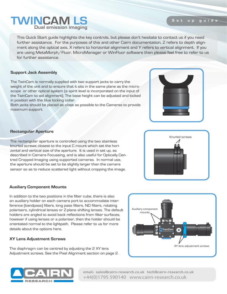
TWINCAM LS Dual emission imaging S e t u p g u i d e This Quick Start guide highlights the key controls, but please don't hesitate to contact us if you need further assistance. For the purposes of this and other Cairn documentation, Z refers to depth alignment along the optical axis, X refers to horizontal alignment and Y refers to vertical alignment. If you are using MetaMorph/Fluor, MicroManager or WinFluor software then please feel free to refer to us for further assistance. Support Jack Assembly The TwinCam is normally supplied with two support jacks to carry the weight of the unit and to ensure that it sits in the same plane as the microscope or other optical system (a spirit level is incorporated on the input of the TwinCam to aid alignment). The base height can be adjusted and locked in position with the blue locking collar. Both jacks should be placed as close as possible to the Cameras to provide maximum support. Rectangular Aperture Knurled screws The rectangular aperture is controlled using the two stainless knurled screws closest to the input C mount which set the horizontal and vertical size of the aperture. It is used in set up, as described in Camera Focussing, and is also useful for Optically Centred Cropped Imaging using supported cameras. In normal use, the aperture should be set to be slightly larger than the camera sensor so as to reduce scattered light without cropping the image. Auxiliary Component Mounts In addition to the two positions in the filter cube, there is also an auxiliary holder on each camera port to accommodate interference (bandpass) filters, long pass filters, ND filters, rotating polarisers, cylindrical lenses or Z-plane shifting lenses. The default holders are angled to avoid back reflections from filter surfaces, however if using lenses or a polariser, then the holder should be orientated normal to the lightpath. Please refer to us for more details about the options here. Auxiliary component mounts TwinCam cairn-research.co.uk XY Lens Adjustment Screws The diaphragm can be centred by adjusting the 2 XY lens Adjustment screws. See the Pixel Alignment section on page 2. XY lens adjustment screws email: sales@cairn-research.co.uk tech@cairn-research.co.uk +44(0)1795 590140 www.cairn-research.co.uk Camera Focusing The TwinCam is factory calibrated and tested, but a user adjustable fine focus is provided to allow for any variability in sensor Z position between cameras. The following procedure should be followed for final optimisation: 1. Insert the Calibration cube into the TwinCam (this splits the light equally between the two camera ports). 2. Power up the cameras and launch your software to display live images. 3. Reduce the size of the rectangular aperture so that it is clearly visible within the camera images. Focus each camera by adjusting the knurled focus ring for the corresponding output port until the edges of the aperture are as sharp as possible (do not worry about the X-Y alignment between the cameras at this stage). The microscope or camera lens should then be adjusted to bring a high contrast object into focus at the same point as the aperture. The system is now infinity corrected. Pixel Alignment The TwinCam LS allows fine X-Y alignment of both transmitted and reflected ports. Firstly the transmitted port should be centred: (1) Set the rectangular aperture so that it's edges are visible within the camera frame. (2) Adjust the two XY lens adjustment screws until the aperture is optimally centred in the image. (3) Adjust the rotation of the camera until the aperture image is parallel to the camera sensor (most software allows a rectangular region of interest to be superimposed on the image to aid alignment). XY lens adjustment screws V H Next centre the reflected port: (1) Adjust the angle of the beamsplitter using the adjustment screws marked H & V on the main body to centre the aperture (this will produce a mirror image of the transmitted camera). (2) Adjust the software to mirror the reflected image and ensure that the sample is clearly in focus on both cameras. (3) Overlay the two images in software and make fine adjustments to pixel align the two channels. (4) Swap the calibration cube for the required beamsplitter and make any final adjustments of the H & V and focus controls in the event of any small lateral or focal shifts. The focussing rings can then be locked in place with the appropriate hex screws and should not need further adjustment. Filter Cube Please note the arrow should be orientated into the filter cube and towards the light path Place the dichroic holding spring in the recess CAIRN www.cairn-re Remove the 4 screws and separate the two halves Remove the dichroic holding spring Installing Dichroic Mirrors into the Cube search.co.u k CAIRN www.cairn-re search.co.u k CAIRN www.cairn-re search.co.u k Remove the top half and resecure. screws Turn the locking ring anticlockwise to remove it Carefully place the filter inside the recess Replace the locking ring and rotate it clockwise to secure Installing Filters into the Cairn Filter Cube email: sales@cairn-research.co.uk tech@cairn-research.co.uk +44(0)1795 590140 www.cairn-research.co.uk

