捷多邦,您值得信赖的PCB打样专家!
Circuit Note
CN-0311
Devices Connected/Referenced
Circuits from the Lab™ reference circuits are engineered and
tested for quick and easy system integration to help solve today’s
analog, mixed-signal, and RF design challenges. For more
information and/or support, visit www.analog.com/CN0311.
ADF4351
Fractional-N PLL IC with Integrated VCO
ADL5385
Wideband Transmit Modulator
ADP150
Low Noise 3.3 V LDO
ADP3334
Low Noise Adjustable LDO
Broadband, Low Error Vector Magnitude (EVM) Direct Conversion Transmitter Using
LO Divide-by-2 Modulator
EVALUATION AND DESIGN SUPPORT
CIRCUIT FUNCTION AND BENEFITS
Circuit Evaluation Boards
ADF4351 Evaluation Board (EVAL-ADF4351EB1Z)
ADL5385 Evaluation Board (ADL5385-EVALZ)
Design and Integration Files
Schematics, Layout Files, Bill of Materials
This circuit is a complete implementation of the analog portion of a
broadband direct conversion transmitter (analog baseband in, RF
out). RF frequencies from 30 MHz to 2.2 GHz are supported by
using a phase-locked loop (PLL) with a broadband integrated
voltage controlled oscillator (VCO). Unlike modulators that use a
divide-by-1 local oscillator (LO) stage (as described in CN-0285),
harmonic filtering of the LO is not required.
ADP150
5.5V
ADP3334
5.5V
1µF
1µF
1µF
1µF
3.3V
5.0V
VVCO
VDD
16
17
VVCO
28
26
4
10
DVDD AVDD
I/Q SMA INPUTS
6
CE PDB RF VP
32
SDV DD
VPS1, VPS2
1nF 1nF
FREF IN
RFOUTB+ 14
VVCO
IBBN
RFOUTB– 15
1 CLK
2 DATA
ZBIAS
ZBIAS
3 LE
SPI-COMPATIBLE SERIAL BUS
ADL5385
IBBP
29 REF IN
51Ω
LOIP
RFOUTA+ 12
ADF4351
1nF
22 RSET
4.7kΩ
LOIN
RFOUTA– 13
DIVIDE-BY-2
QUADRATURE
PHASE
SPLITTER
RFOUT
1nF
VTUNE 20
QBBP
180Ω
CPOUT 7
QBBN
330nF
22nF
SW 5
8
SDGND AGND
31
9
AGNDVCO
11 18
21
DGND
27
I/Q SMA INPUTS
11268-001
CPGND
10nF
82Ω
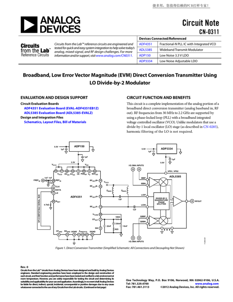
Figure 1. Direct Conversion Transmitter (Simplified Schematic: All Connections and Decoupling Not Shown)
Rev. 0
Circuits from the Lab™ circuits from Analog Devices have been designed and built by Analog Devices
engineers. Standard engineering practices have been employed in the design and construction of
each circuit, and their function and performance have been tested and verified in a lab environment at
room temperature. However, you are solely responsible for testing the circuit and determining its
suitability and applicability for your use and application. Accordingly, in no event shall Analog Devices
be liable for direct, indirect, special, incidental, consequential or punitive damages due to any cause
whatsoever connected to the use of any Circuits from the Lab circuits. (Continued on last page)
One Technology Way, P.O. Box 9106, Norwood, MA 02062-9106, U.S.A.
Tel: 781.329.4700
www.analog.com
Fax: 781.461.3113
©2012 Analog Devices, Inc. All rights reserved.
CN-0311
Circuit Note
The circuit shown in Figure 1 uses the ADF4351, a fully integrated
fractional-N PLL IC, and the ADL5385 wideband transmit
modulator. The ADF4351 provides the local oscillator (the LO is
twice the modulator RF output frequency) signal for the ADL5385
transmit quadrature modulator, which upconverts the analog
I/Q signals to RF. Taken together, the two devices provide a
wideband, baseband I/Q-to-RF transmit solution.
The ADF4351 is powered off the ultralow noise 3.3 V ADP150
regulator for optimal LO phase noise performance. The ADL5385
is powered off a 5 V ADP3334 LDO. The ADP150 LDO has an
output voltage noise of only 9 µV rms, integrated from 10 Hz to
100 kHz, and helps to optimize VCO phase noise and reduce
the impact of VCO pushing (equivalent to power supply
rejection). See CN-0147 for more details on powering the
ADF4351 with the ADP150 LDO.
The ADL5385 uses a divide-by-2 block to generate the quadrature
LO signals. The quadrature accuracy is, thus, dependent on the
duty cycle accuracy of the incoming LO signal (as well as the
matching of the internal divider flip-flops). Any imbalance in
the rise and fall times causes even-order harmonics to appear, as
evident on the ADF4351 RF outputs. When driving the modulator
LO inputs differentially, even-order cancellation of harmonics
is achieved, improving the overall quadrature generation. (See
“Wideband A/D Converter Front-End Design Considerations:
When to Use a Double Transformer Configuration.” Rob
Reeder and Ramya Ramachandran. Analog Dialogue, 40-07.)
Because sideband suppression performance is dependent on the
modulator quadrature accuracy, better sideband suppression is
achievable when driving the LO input ports differentially vs.
single-ended. The ADF4351 has differential RF outputs compared
to the single-ended output available on most of the competitor’s
PLL devices with integrated VCOs.
A sweep of sideband suppression vs. RF output frequency is shown
in Figure 2. In this sweep, the test conditions were as follows:
•
Baseband I/Q amplitude = 1.4 V p-p differential sine waves
in quadrature with a 500 mV dc bias
Baseband I/Q frequency (fBB) = 1 MHz
LO = 2 × RFOUT
•
•
A simplified diagram of the test setup is shown in Figure 3. A
modified ADL5385 evaluation board was used because the
standard ADL5385 board does not allow a differential LO
input drive.
0
DATA SHEET SPECIFICATION
–10
–20
–30
–40
–50
–60
–70
0
500
1000
1500
2000
FREQUENCY (MHz)
11268-002
CIRCUIT DESCRIPTION
The ADF4351 output match consists of the ZBIAS pull-up and,
to a lesser extent, the decoupling capacitors on the supply node.
To get a broadband match, it is recommended to use either a
resistive load (ZBIAS = 50 Ω) or a resistive in parallel with a reactive
load for ZBIAS. The latter gives slightly higher output power,
depending on the inductor chosen. Use an inductor value of
19 nH or greater for LO operation below 1 GHz. The measured
results in this circuit were performed using ZBIAS = 50 Ω and an
output power setting of 5 dBm. When using the 50 Ω resistor,
this setting gives approximately 0 dBm on each output across
the full band, or 3 dBm differentially. The ADL5385 LO input
drive level specification is −10 dBm to +5 dBm; therefore, it is
possible to reduce the ADF4351 output power to save current.
SIDEBAND SUPPRESSION (dBc)
To achieve optimum performance, the only requirement is that the
LO inputs of the modulator be driven differentially. The ADF4351
provides differential RF outputs and is, therefore, an excellent
match. This PLL-to-modulator interface is applicable to all I/Q
modulators and I/Q demodulators that contain a 2XLO-based
phase splitter. Low noise LDOs ensure that the power management
scheme has no adverse impact on phase noise and error vector
magnitude (EVM). This combination of components represents
an industry-leading direct conversion transmitter performance
over a frequency range of 30 MHz to 2.2 GHz. For frequencies
above 2.2 GHz, it is recommended to use a divide-by-1 modulator,
as described in CN-0285.
Figure 2. Sideband Suppression, RFOUT Swept from 30 MHz to 2200 MHz
This circuit achieves comparable or improved sideband
suppression performance when compared to driving the
ADL5385 with a low noise RF signal generator, as used in the
data sheet measurement. Using the differential RF outputs of
the ADF4351 provides even-order harmonic cancellation and
improves modulator quadrature accuracy. This affects sideband
suppression performance and EVM. A single carrier W-CDMA
composite EVM of better than 2% was measured with the circuit
shown in Figure 1. The solution thus provides a low EVM broadband solution for frequencies from 30 MHz to 2.2 GHz. For
frequencies above 2.2 GHz, use a divide-by-1 modulator
block, as described in CN-0285.
The complete design support package can be found at
http://www.analog.com/CN0311-DesignSupport.
Rev. 0 | Page 2 of 4
Circuit Note
CN-0311
R&S AMIQ
IP
RFOUTA+
QP
QN
ADL5385 EVALUATION BOARD
ADAPTED TO ACCEPT
RFOUT
DIFFERENTIAL LO INPUTS
ADF4351
EVALUATION BOARD
RFOUTA–
IN
LOIP
SPECTRUM
ANALYZER
LOIN
11268-003
5V
POWER SUPPLY
Figure 3. Sideband Suppression Measurement Test Setup (Simplified Diagram)
COMMON VARIATIONS
Getting Started
The PLL-to-modulator interface described is applicable to all
I/Q modulators that contain a 2XLO-based phase splitter. It is
also applicable to 2XLO-based I/Q demodulators, such as the
ADL5387.
A description of the circuit, the schematic, and a block diagram
of the test setup is detailed within the CN-0311 (see Figure 1 and
Figure 3). The UG-435 user guide details the installation and use of
the EVAL-ADF4351EB1Z evaluation software. The UG-435 also
contains the board setup instructions, and the board schematic,
layout, and bill of materials. The ADL5385-EVALZ board
schematic, block diagram, bill of materials, layout, and assembly
information is included in the ADL5385 data sheet. See the
ADF4351 data sheet and ADL5385 data sheet for device
information.
CIRCUIT EVALUATION AND TEST
The CN-0311 uses the EVAL-ADF4351EB1Z and the ADL5385EVALZ for the evaluation of the described circuit, allowing for
quick setup and evaluation. The EVAL-ADF4351EB1Z uses
the standard ADF4351 programming software contained on the
CD that accompanies the evaluation board.
Equipment Needed
Functional Block Diagram
The following equipment is needed:
The functional block diagram of the described test setup is
shown in Figure 3.
•
Setup and Test
•
•
•
•
•
•
A PC with a USB port that contains Windows® XP, Vista, or
Windows 7
The EVAL-ADF4351EB1Z evaluation board
The ADL5385-EVALZ evaluation board,
ADF4351 programming software
Power supplies (5 V, 500 mA)
An I-Q signal source, such as a Rohde & Schwarz AMIQ
A spectrum analyzer
After setting up the equipment, use standard RF test methods to
measure the sideband suppression of the circuit.
Also, see the UG-435 User Guide for the EVAL-ADF4351EB1Z
evaluation board, the ADF4351 data sheet, and the ADL5385
data sheet.
Rev. 0 | Page 3 of 4
CN-0311
Circuit Note
LEARN MORE
Data Sheets and Evaluation Boards
CN0311 Design Support Package:
http://www.analog.com/CN0311-DesignSupport
ADF4351 Data Sheet
ADIsimPLL Design Tool
ADL5385 Data Sheet
ADIsimPower Design Tool
ADL5385 Evaluation Board
ADIsimRF Design Tool
ADP150 Data Sheet
Brandon, David, David Crook, and Ken Gentile. AN-0996
Application Note, The Advantages of Using a Quadrature
Digital Upconverter (QDUC) in Point-to-Point Microwave
Transmit Systems. Analog Devices.
ADP3334 Data Sheet
ADF4351 Evaluation Board
REVISION HISTORY
12/12—Revision 0: Initial Version
CN-0134, Broadband Low EVM Direct Conversion Transmitter.
Analog Devices.
CN-0147, Using the ADP150 LDO Regulators to Power the
ADF4350 PLL and VCO. Analog Devices.
Nash, Eamon. AN-1039 Application Note, Correcting
Imperfections in IQ Modulators to Improve RF Signal
Fidelity. Analog Devices.
Reeder, Rob, and Ramya Ramachandran. “Wideband A/D
Converter Front-End Design Considerations: When to
Use a Double Transformer Configuration.” Analog
Dialogue, 40-07.
(Continued from first page) Circuits from the Lab circuits are intended only for use with Analog Devices products and are the intellectual property of Analog Devices or its licensors. While you
may use the Circuits from the Lab circuits in the design of your product, no other license is granted by implication or otherwise under any patents or other intellectual property by
application or use of the Circuits from the Lab circuits. Information furnished by Analog Devices is believed to be accurate and reliable. However, Circuits from the Lab circuits are supplied
"as is" and without warranties of any kind, express, implied, or statutory including, but not limited to, any implied warranty of merchantability, noninfringement or fitness for a particular
purpose and no responsibility is assumed by Analog Devices for their use, nor for any infringements of patents or other rights of third parties that may result from their use. Analog Devices
reserves the right to change any Circuits from the Lab circuits at any time without notice but is under no obligation to do so.
©2012 Analog Devices, Inc. All rights reserved. Trademarks and
registered trademarks are the property of their respective owners.
CN11268-0-12/12(0)
Rev. 0 | Page 4 of 4


