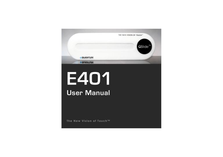
E401
User Manual
The New Vision of Touch™
E401
User Manual
OVERVIEW
This kit is designed for evaluation and development of QT401-based QSlide™ slider
controls. It includes a fully assembled slider PCB, demo control panel, cables and
software. The E401 has serial interface allowing connection to a PC for control and data
viewing via an included USB to SPI adapter and PC software.
For more detailed information about this product please refer to the QT401 datasheet.
Materials Provided:
1 x White plastic slider demo panel
1 x E401 evaluation board with self-adhesive on one side
6 x Rubber feet
1 x USB-PC cable
1 x USB-SPI adapter with USB-SPI cable to the E401
1 x Spare SPI cable for user connection to a microcontroller
2 x Sample QT401-IS ICs
1 x CD-ROM with QSlide™ software and USB drivers
1 x User Guide
CONTENTS
BOARD PREPARATION
Page 2
RUNNING THE E401
Page 3
QSLIDE™ SOFTWARE OPERATION Page 4
BOARD DETAILS
Page 6
SCHEMATIC DIAGRAM
Page 8
PCB LAYOUT
Page 9
SOFTWARE INSTALLATION (CD)
Page 10
SOFTWARE INSTALLATION (WEB)
Page 11
REAL WORLD APPLICATION
Page 12
TROUBLESHOOTER
Inside Back Cover
1
BOARD PREPARATION
2
The E401 PCB can be adhered to plastic, glass, or any other dielectric panel. A white
sample panel is included. Please follow these steps to mount the E401 PCB to the sample
panel:
1
Use normal ESD precautions when working with the E401 !!
2
Place the user panel face down on a table —
Tape down the edges of the panel to the table so it cannot move while you work with it.
3
Remove the paper backing from the E401 PCB and adhere it to the rear of the user panel.
Bend the PCB slightly as shown while smoothing it to remove any air bubbles.
Tip: Line up the PCB with the alignment marks on the back of the slider panel. The PCB
must be positioned with the connector on the underside of the QSlide™ logo. The
PCB does allow some flexing, but care must be taken not to bend it too far as this can crack
the SMT components.
4
Mount the 6 rubber feet as shown to make the E401 mechanically stable in use.
RUNNING THE E401
3
To Run the E401, Please Follow These Steps:
1 IMPORTANT: First install QSlide™ software and USB drivers (see page 10).
2
3
4
5
6
7
8
Make sure the USB adapter box is NOT plugged into your PC at this time.
Connect the E401 to the USB box with the red USB-SPI cable
Connect the USB adapter to your running PC and wait at least 10 seconds so that the
USB adaptor is properly recognized. The USB box’s LED should come on solid.
Run the QSlide™ software (Qslide_V[x].exe) which should be on your desktop or other
location where you copied it. See next page for details.
With your hands far removed from the E401: Click on the FIXED CAL button first, then
after 1 or 2 seconds, the ADAPTIVE CAL button.
Slowly move your hand towards the slider. The proximity alert status box will indicate
when your hand is still several cm away from the panel.
Touch the slider area with a finger. You can either slide your finger across the surface or
touch the slider at any point. When you remove your finger, the last position touched will
be locked on the display.
Things to Try:
— Alter the proximity and detect thresholds using the pull down menus to change the sensitivity to
proximity and touch. The higher the threshold, the less sensitive the E401 will become.
— Change the rate of environmental drift compensation with the DRIFT RATE dropdown. This
affects how fast the sensor will compensate for slow environmental changes. Normally this should
be set to a very slow rate (once per 3 or 4 seconds). Faster rates can cause complications with
proximity and touch detection.
4
QSLIDE™ SOFTWARE OPERATION
Warning: Disconnecting the USB cable from the PC while QSlide software is
communicating with the E401 board may crash the software. Please close the
QSlide software before unplugging the USB cable.
QSlide software should automatically detect the correct com port; if not, you may need to select
the port manually as shown below. If the correct port (usually a com port higher than 3) does not
appear, close the program, wait 30 seconds, and try again — Windows may be slow to recognize
the USB hardware.
5
Prox Detection indicates that the
board has detected a hand at a
distance.
Slider Detection indicates that the
board is detecting a finger touch.
Changing the associated threshold
sets the amount of signal change
which will cause the E401 to register
touch. Default = 25
The Prox value sets the threshold
which will cause the chip to register
proximity; lower numbers are more
sensitive. Default = 3
Signal Error indicates that the signal
has the wrong polarity, usually due to
board movement.
Calibration should be performed with
the PCB in the intended position in
which it will be used, with hands at a
distance, to get a valid reference level.
Clicking the Fixed Cal then
Adaptive Cal buttons will resolve the
error.
Once positioned, the board should be
calibrated using the Fixed Cal button.
Note: Fixed Cal must precede Adaptive Cal, otherwise the end calibrations
will be inaccurate.
Drift Rate sets the adaptive drift
compensation rate; the numbers
represent seconds per
compensation.
Clicking Fixed Cal alone will cancel
Adaptive Cal.
If the board is moved it may need to
be recalibrated.
Output Ratio shows the numerical
slider position, from 0 (left) to 127
(right).
If any status flags are set prior to
operation then calibration should
be repeated.
Clicking Adaptive Cal causes the
E401 to match the electrical endpoints to the physical ends using a
special calibration process.
Do this only after clicking Fixed Cal.
Command Return represents the
QT401’s response status byte in
hexadecimal. This is useful for
diagnostic purposes.
Slider Bar shows the reported position of
touch. This bar does not move when only
proximity is detected. It will lock on the
last reported position after touch is lifted.
6
BOARD DETAILS
SPI Interface Connector
This connector provides all signals and power needed to communicate with the USB adapter or
an external host such as a microcontroller.
See Table 1 (next page) for a description of the connector pinout.
Voltage Regulator
The E401 uses a low drop out regulator to regulate the 5V coming from the USB adapter box
down to 3.3V. Resistor R25 is used to provide a minimum load on the regulator when the QT401
goes to sleep between acquisitions; this is necessary for regulator transient stability.
Since the QT401 works on a lower voltage (3.3V) than the USB box (5.0V), the signals from the
USB box to the E401 must be level shifted down. This is done using resistive dividers consisting
of 1K resistors R20, R21 and R22, plus a set of 560 ohm resistors placed in series with the signal
lines inside the USB box.
Slider Element
The capacitive slider consists of the 17 resistors R2...R18 and the copper pads they connect.
The end–to-end resistance of the slider element is about 95K ohms. Resistors R1 and R19 are
zero ohms but can be changed to allow manual trimming of the end-positions of the slider if
adaptive calibration is not used. Increasing R1 and/or R19 will move the ends outwards.
Sampling Capacitors
C1 and C2 are the Cs sampling capacitors; increasing their value will increase sensitivity and
resolution of measurement, but will also tend to make for a slower response time.
7
Figure 1 — Board Layout
CON1, Pin # 1 This Side
QT401 IC
Slider Element
Table 1 — Connector (CON1) Pin List
Pin
Description
1
0V (Ground)
2
+5V power
3
+5V power
4
DRDY—data ready (output)
5
SDO—serial data (output)
6
/SS—slave select (input)
7
SCLK—serial clock (input)
8
SDI—serial data (input)
9
Detect—active high (output)
10
Prox—active high (output)
SCHEMATIC DIAGRAM
8
Figure 2 —
Schematic
Diagram
PCB LAYOUT
Figure 3 — Silk Layer
Figure 4 — Top Layer
Table 2 — Operating Range
Temperature
-20°C to +60°C
Supply Voltage
4.75-15VDC
9
10
SOFTWARE INSTALLATION (CD)
If you have a Quantum CD-ROM, follow these steps to install QSlide™ software and USB
drivers. If you previously installed such drivers, do not install them again. If you
experience problems, make sure you have administrative rights (e.g. under XP Pro).
Install the QSlide™ Signal Viewing Software
To install the QSlide™ viewing software, simply copy the file Qslide_V[x].exe from the supplied
CD to your Windows Desktop. The software can be found on the CD in folder D:\SOFTWARE\
(replace D: with the actual drive letter of your CD)
Install the USB Drivers
Place the CD-ROM in your CD drive.
Connect the USB adapter box to the
PC using the supplied USB cable. The
E401 may be connected (or not).
Windows will display the Found New
Hardware Wizard for the
USB <-> Serial Cable. Select Install
the software automatically and click
Next. Windows now installs the
drivers. Click Finish when prompted.
The Found New Hardware Wizard
will appear again for the USB Serial
Port device. Simply repeat the above
steps again.
Windows may prompt you to restart your PC at this point; restarting is not necessary.
You are now done with the software and driver installation. Go back to page 3.
SOFTWARE INSTALLATION (WEB)
11
Follow these steps to install QSlide™ software and USB drivers from www.qprox.com. If
you previously installed such drivers, do not install them again. If you experience
problems, make sure you have administrative rights (e.g. under XP Pro).
Create New Folder C:\QRG-USB
Create a new temporary folder to hold the files you are about to download, called C:\QRG-USB
Download and Extract the Files
Go to www.qprox.com/software and click on the file qrg-usb_drivers.zip and click Save; save
the file to C:\QRG-USB. Extract all files inside qrg-usb_driver.zip within folder C:\QRG-USB.
Now, download QSlide™ software (Qslide_V[x].exe) but save this to your Windows Desktop.
Install the USB Drivers
Follow the USB directions on page 10 except:
When the Found New Hardware Wizard
appears, select Install from a list or specific
location. Then, specify the location as
C:\QRG-USB and click Next.
Windows will now install the drivers.
Click Finish when prompted.
The Found New Hardware Wizard will appear
again for the USB Serial Port device. Simply
repeat the above steps again.
You may be prompted to restart your PC;
restarting is not necessary. You may now delete the
temporary folder C:\QRG-USB.
You are now done with the software and driver installation. Go back to page 3.
12
REAL WORLD APPLICATION
QSlide™ Concept
Cooktop
This concept cooktop was modified from a
commercially available unit to demonstrate
several advanced Quantum touch control
features.
A central feature is the QSlide™ control used to
dial in the power level from 0 to 99. The single
slider is shared among the four burners by
means of 4 burner select buttons and 4 LED
power displays. Touching one of these 4 burner
buttons enables the slider to control the power
level on that burner. The 2-digit LED for that
burner tracks the power level setting.
The power button
features a unique,
patent-pending,
‘slide-on’ touch
method that helps
prevent accidental
operation.
Another advanced feature is a unique ‘slide-on’
touch control switch that is child-resistant yet
easy for an adult to use. It operates much like a
conventional slide switch: sliding your finger up
turns on the appliance. Turning the appliance off
is easy: just touch anywhere in the power button
area.
This cooktop uses both QTouch™ and QSlide™
technologies. QTouch™ and QSlide™
technology are patented and patent pending
worldwide.
The slider control is shared among the four
burners. Touch one of the four burner touch
buttons, and the LEDs for that burner
become brighter. The slider will then work to
change power level for that burner.
TROUBLESHOOTER
Board Will
Not
Communicate
with PC
Bad SPI or USB Connections
Check/replace cables
Make sure the board is getting power and USB light is on solid
Bad or Conflicting Virtual Comm Port on PC
See the Software Installation section - reinstall driver software, or,
change the USB-Serial com port number in Device Manager if there
is a conflict
LED Flashes on USB Adapter (USB box not recognized)
Disconnect and reconnect the board and USB adapter, take care to
connect the QSlide™ board to the USB adapter first as USB box
detects the QSlide™ board on power up.
Board will not Calibrate due to noise (failure to calibrate will cause the board
to cease communications)
See below — Noisy or erratic signal
Noisy or
Erratic Signal
Noisy Power Supply - try a different USB port or PC
Cables or Board too Close to Strong Noise Source (such as a power line or
switching noise source)
Increase the distance from E401 to the noise source
Place a grounded metal shield between the noise source and the
QSlide™ board
QSlide™ Board is not Mechanically Stable
Prevent board from moving around
Strong RFI from a Transmitter or Adjacent Digital Product
Remove the noise source or shield against it
LQ
w w w . q p r o x . c o m
Development Team: Martin Simmons, Luben Hristov, Samuel Brunet
Corporate Headquarters
North America
1 Mitchell Point
Ensign Way, Hamble
Southampton SO31 4RF
United Kingdom
651 Holiday Drive Bldg. 5 / 300
Pittsburgh, PA 15220
USA
Tel
Fax
+44 (0)23 8056 5600
+44 (0)23 8045 3939
Email sales1@qprox.com
Tel
Fax
412-391-7367
412-291-1015
Copyright © 2004 QRG Ltd
All rights reserved
Patented and patents pending
REV 102.070904


