Fusing Equipment
Electrical Apparatus
240-47
Isolation Link
GENERAL
Cooper Power Systems isolation links
provide extra protection during refusing
and switching operations when used in
series with a Bay-O-Net type fuse or
MagneX Interrupter.
Isolation links are not fuses and do not
have an interrupting rating. During a
transformer failure, the isolation link will
melt so that the opened primary circuit
of a faulted transformer cannot be
re-energized by the line crew.
APPLICATIONS
Bay-O-Net Assemblies
Isolation links are used in series with
Cooper Power Systems Bay-O-Net
type expulsion fuses to provide extra
protection during re-fusing operations.
They are coordinated to operate at
high current levels that are typical of a
transformer failure.
MagneX Interrupter
Isolation links are also used in series
with the Cooper Power Systems
MagneX Interrupter to provide extra
protection during switching operations.
The MagneX isolation link has arc
shortening tabs to reduce the arc
length and thus reduce the I2t energy
released during operation. They are
coordinated to operate at high current
levels that are typical of a transformer
failure.
INSTALLATION
No special tools are required. Isolation
links are bolted onto Bay-O-Net fuse
assemblies or MagneX Interrupters in
series between the primary transformer
bushing and primary coil. Refer to
Installation Instruction Sheet S24040-2, Bay-O-Net, and S240-34-1,
MagneX Interrupter, for details.
ORDERING INFORMATION
To order Cooper Power Systems
Isolation Link, first refer to Sections
240-45 (current sensing) 240-46 (dual
sensing), 240-48 (dual element) or
240-49 (high ampere overload) for
details on corresponding Cooper
Power Systems Bay-O-Net fuse or
Section 240-34 for details on MagneX
Interrupter elements. For the fuse
elements, use Table 1 to cross
reference the isolation link required. For
the MagneX Interrupter elements, use
May 2010 • Supersedes 2/96
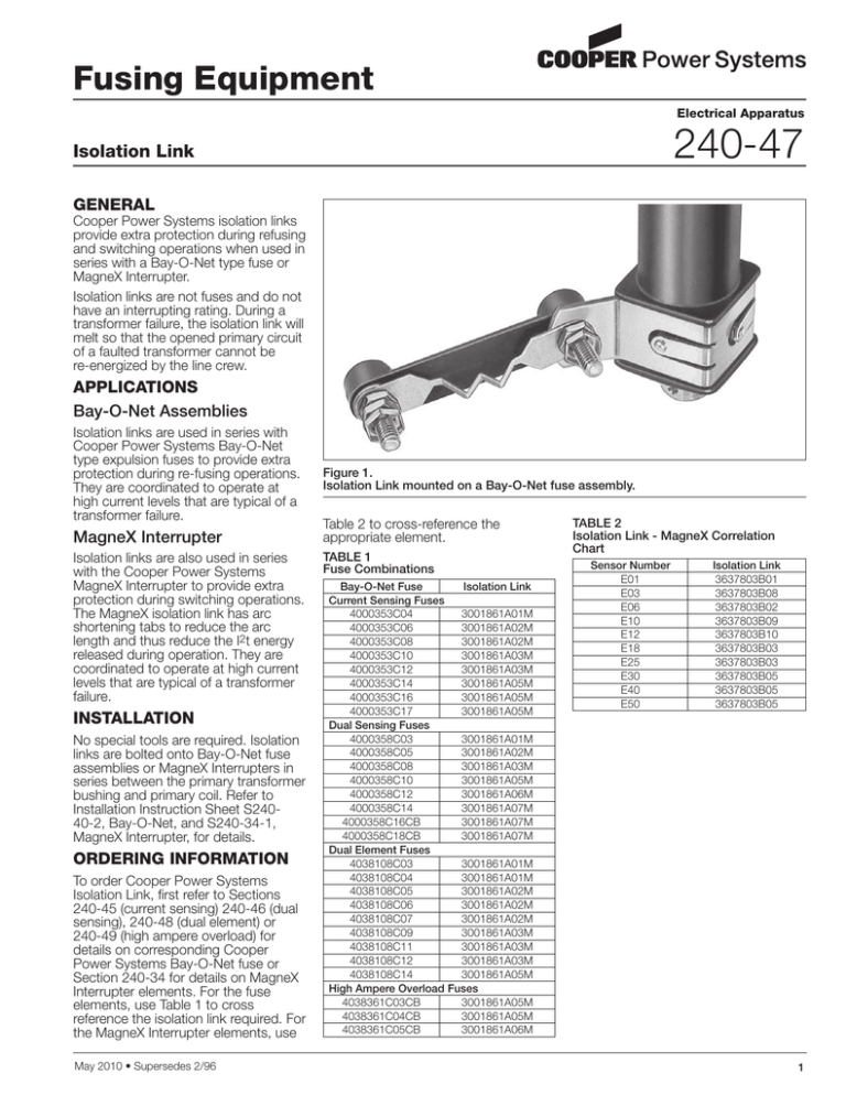
Figure 1.
Isolation Link mounted on a Bay-O-Net fuse assembly.
Table 2 to cross-reference the
appropriate element.
TABLE 1
Fuse Combinations
Bay-O-Net Fuse
Isolation Link
Current Sensing Fuses
4000353C04
3001861A01M
4000353C06
3001861A02M
4000353C08
3001861A02M
4000353C10
3001861A03M
4000353C12
3001861A03M
4000353C14
3001861A05M
4000353C16
3001861A05M
4000353C17
3001861A05M
Dual Sensing Fuses
4000358C03
3001861A01M
4000358C05
3001861A02M
4000358C08
3001861A03M
4000358C10
3001861A05M
4000358C12
3001861A06M
4000358C14
3001861A07M
4000358C16CB
3001861A07M
4000358C18CB
3001861A07M
Dual Element Fuses
4038108C03
3001861A01M
4038108C04
3001861A01M
4038108C05
3001861A02M
4038108C06
3001861A02M
4038108C07
3001861A02M
4038108C09
3001861A03M
4038108C11
3001861A03M
4038108C12
3001861A03M
4038108C14
3001861A05M
High Ampere Overload Fuses
4038361C03CB
3001861A05M
4038361C04CB
3001861A05M
4038361C05CB
3001861A06M
TABLE 2
Isolation Link - MagneX Correlation
Chart
Sensor Number
E01
E03
E06
E10
E12
E18
E25
E30
E40
E50
Isolation Link
3637803B01
3637803B08
3637803B02
3637803B09
3637803B10
3637803B03
3637803B03
3637803B05
3637803B05
3637803B05
1
Features and Detailed Description
ISOLATION LINK
Isolation Link
coordinated to melt
on transformer
faults.
2.5"
(64 mm)
3.1"
(79 mm)
BRACKET
High temperature
thermoplastic
withstands
transformer
operating
temperatures.
0.44"
(11 mm)
0.63"
(16 mm)
0.91"
(23 mm)
1.3"
(33 mm)
Figure 2.
Dimensional information of isolation links for Bay-O-Net fuses.
NOTE: Dimensions given are for reference only.
ISOLATION LINK ELEMENT
(2 DIFFERENT ELEMENT SHAPES POSSIBLE)
ARC SHORTENING TABS
2.5"
(64 mm)
.83"
(21 mm)
1.3"
(33 mm)
3.1"
(79 mm)
Figure 3.
Dimensional information of isolation links for MagneX applications.
NOTE: Dimensions given are for reference only.
© 2010 Cooper Industries. All Rights Reserved.
Cooper Power Systems and MagneX are valuable trademarks of Cooper
Industries in the U.S. and other countries. You are not permitted to use the
Cooper Trademarks wiothout the prior written consent of Cooper Industries.
2
2300 Badger Drive
Waukesha, WI 53188 USA
www.cooperpower.com


