Satellite communication 10EC662
advertisement
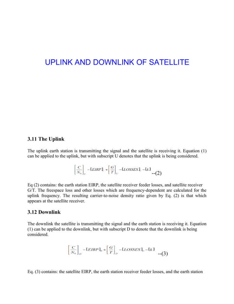
UPLINK AND DOWNLINK OF SATELLITE 3.11 The Uplink The uplink earth station is transmitting the signal and the satellite is receiving it. Equation (1) can be applied to the uplink, but with subscript U denotes that the uplink is being considered. --(2) Eq (2) contains: the earth station EIRP, the satellite receiver feeder losses, and satellite receiver G/T. The freespace loss and other losses which are frequency-dependent are calculated for the uplink frequency. The resulting carrier-to-noise density ratio given by Eq. (2) is that which appears at the satellite receiver. 3.12 Downlink The downlink the satellite is transmitting the signal and the earth station is receiving it. Equation (1) can be applied to the downlink, but with subscript D to denote that the downlink is being considered. --(3) Eq. (3) contains: the satellite EIRP, the earth station receiver feeder losses, and the earth station receiver G/T. The free-space and other losses are calculated for the downlink frequency. The resulting carrier-to-noise density ratio given by Eq. (3) is that which appears at the detector of the earth station receiver. Where the carrier-to-noise ratio is the specified quantity rather than carrier-to-noise density ratio, Eq. (1) is used. On assuming that the signal bandwidth B is equal to the noise bandwidth BN, we obtain: --(4) 3.13 Combined Uplink and Downlink C/N Ratio The complete satellite circuit consists of an uplink and a downlink, as sketched in Fig.3.1 Fig 3.1 (a) combined uplink and downlink (b) power flow diagram Noise will be introduced on the uplink at the satellite receiver input. PNU = noise power per unit bandwidth PRU = average carrier at the same point The carrier-to-noise ratio on the uplink is Note that power levels, and not decibels, are being used. PR = carrier power at the end of the space link = the received carrier power for the downlink. = K x the carrier power input at the satellite Where K = the system power gain from satellite input to earth station input. This includes the satellite transponder and transmit antenna gains, the downlink losses, and the earth station receive antenna gain and feeder losses. The noise at the satellite input also appears at the earth station input multiplied by K, and in addition, the earth station introduces its own noise, denoted by PND. Thus the end-of-link noise is KPNU + PND. The C/No ratio for the downlink alone, not counting the KPNU contribution, is PR/PND, and the combined C/No ratio at the ground receiver is PR/(KPNU + PND). The power flow diagram is shown in Fig. 3.1 b. The combined carrier-to-noise ratio can be determined in terms of the individual link values. To show this, it is more convenient to work with the noise-to-carrier ratios rather than the carrier-tonoise ratios, and these must be expressed as power ratios, not decibels. Denoting the combined noise-to-carrier ratio value by No/C, the uplink value by (No/C)U, and the downlink value by (No/C)D then, --(4) Equation (4) shows that to obtain the combined value of C/N0, the reciprocals of the individual values must be added to obtain the N0/C ratio and then the reciprocal of this taken to get C/N0. The reason for this reciprocal of the sum of the reciprocals method is that a single signal power is being transferred through the system, while the various noise powers which are present are additive. Similar reasoning applies to the carrier-to-noise ratio, C/ N. Source : http://elearningatria.files.wordpress.com/2013/10/ece-vi-satellite-communications-10ec662-notes.pdf
