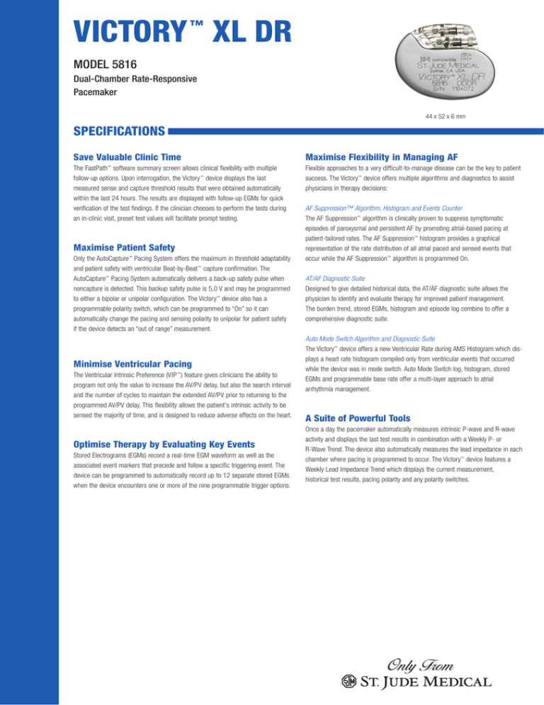
VICTORY XL DR
™
MODEL 5816
Dual-Chamber Rate-Responsive
Pacemaker
44 x 52 x 6 mm
SPECIFICATIONS
Save Valuable Clinic Time
Maximise Flexibility in Managing AF
The FastPath™ software summary screen allows clinical flexibility with multiple
follow-up options. Upon interrogation, the Victory ™ device displays the last
measured sense and capture threshold results that were obtained automatically
within the last 24 hours. The results are displayed with follow-up EGMs for quick
verification of the test findings. If the clinician chooses to perform the tests during
an in-clinic visit, preset test values will facilitate prompt testing.
Flexible approaches to a very difficult-to-manage disease can be the key to patient
success. The Victory™ device offers multiple algorithms and diagnostics to assist
physicians in therapy decisions:
Maximise Patient Safety
Only the AutoCapture™ Pacing System offers the maximum in threshold adaptability
and patient safety with ventricular Beat-by-Beat ™ capture confirmation. The
AutoCapture™ Pacing System automatically delivers a back-up safety pulse when
noncapture is detected. This backup safety pulse is 5,0 V and may be programmed
to either a bipolar or unipolar configuration. The Victory™ device also has a
programmable polarity switch, which can be programmed to “On” so it can
automatically change the pacing and sensing polarity to unipolar for patient safety
if the device detects an “out of range” measurement.
Minimise Ventricular Pacing
The Ventricular Intrinsic Preference (VIP ™) feature gives clinicians the ability to
program not only the value to increase the AV/PV delay, but also the search interval
and the number of cycles to maintain the extended AV/PV prior to returning to the
programmed AV/PV delay. This flexibility allows the patient's intrinsic activity to be
sensed the majority of time, and is designed to reduce adverse effects on the heart.
Optimise Therapy by Evaluating Key Events
Stored Electrograms (EGMs) record a real-time EGM waveform as well as the
associated event markers that precede and follow a specific triggering event. The
device can be programmed to automatically record up to 12 separate stored EGMs
when the device encounters one or more of the nine programmable trigger options.
AF Suppression™ Algorithm, Histogram and Events Counter
The AF Suppression™ algorithm is clinically proven to suppress symptomatic
episodes of paroxysmal and persistent AF by promoting atrial-based pacing at
patient-tailored rates. The AF Suppression™ histogram provides a graphical
representation of the rate distribution of all atrial paced and sensed events that
occur while the AF Suppression™ algorithm is programmed On.
AT/AF Diagnostic Suite
Designed to give detailed historical data, the AT/AF diagnostic suite allows the
physician to identify and evaluate therapy for improved patient management.
The burden trend, stored EGMs, histogram and episode log combine to offer a
comprehensive diagnostic suite.
Auto Mode Switch Algorithm and Diagnostic Suite
The Victory™ device offers a new Ventricular Rate during AMS Histogram which displays a heart rate histogram compiled only from ventricular events that occurred
while the device was in mode switch. Auto Mode Switch log, histogram, stored
EGMs and programmable base rate offer a multi-layer approach to atrial
arrhythmia management.
A Suite of Powerful Tools
Once a day the pacemaker automatically measures intrinsic P-wave and R-wave
activity and displays the last test results in combination with a Weekly P- or
R-Wave Trend. The device also automatically measures the lead impedance in each
chamber where pacing is programmed to occur. The Victory™ device features a
Weekly Lead Impedance Trend which displays the current measurement,
historical test results, pacing polarity and any polarity switches.
VICTORY ™ XL DR Model 5816
AF Management
PHYSICAL CHARACTERSTICS
Dimensions (mm)
Weight (g)
Volume (cc)
Connector
44 x 52 x 6
23.5
11*
3.2 mm (IS-1 or VS•1)
PARAMETERS
SETTINGS
AF Suppression™ Algorithm
Lower Rate Overdrive (min -1)
Upper Rate Overdrive (min -1)
No. of Overdrive Pacing Cycles
Rate Recovery (ms)
Maximum AF Suppression Rate (min -1)
Atrial Tachycardia Detection Rate (min-1)
Auto Mode Switch
Rate/Timing
Atrial Absolute Refractory Period
Atrial Protection Interval (ms)
Atrial Refractory (PVARP) (ms)
AV Delay (ms)
Base Rate (bpm)
Far-Field Protection Interval (ms)
Hysteresis Rate (min-1)
Search Interval (min)
Cycle Count
Intervention Rate (min-1)
Intervention Duration (min)
Recovery Time
Maximum Tracking Rate (min-1)
Mode
Post Vent. Atrial Blanking (PVAB) (ms)
PV Delay (ms)
Rest Rate (min-1)
Shortest AV/PV Delay (ms)
Ventricular Blanking (ms)
Ventricular Refractory (ms)
60; 80; 100-350 in steps of 25
125Δ
125-500 in steps of 25; 275
25; 30-200 in steps of 10; 225-300 in steps of 25; 350;
200
30**; 40-130 in steps of 5; 140-170 in steps of 10; 60
16Δ
Off; 30-130 in steps of 5; 140; 150***
Off; 5; 10; 15; 30
1-16 in steps of 1
Off; 60; 80-120 in steps of 10 (Intrinsic +0;
Intrinsic +10; Intrinsic +20; Intrinsic +30)
1-10 in 1 minute intervals
Fast; Medium; Slow; Very Slow
90-130 in steps of 5; 140-180 in steps of 10; 130
AOO(R); AAI(R); AAT(R); OAO; VOO(R); VVI(R);
VVT(R); VDD(R); OVO; DOO(R); DVI(R); DDI(R);
DDD(R); ODO
60; 70; 80; 85; 95; 100; 110; 115; 125; 130; 140;
150; 155; 165; 170; 180; 185; 195; 200
25; 30-200 in steps of 10; 225-325 in steps of 25;
150
Off; 30-130 in steps of 5; 140; 150
30-50 in steps of 5; 60-120 in steps of 10; 100
12-52 in steps of 4; 12
125-500 in steps of 25†; 250
Output/Sensing
A or V Pulse Amplitude (V)
A or V Pulse Width (ms)
A or V Pulse Configuration
A or V Sense Configuration
Atrial Sensitivity (mV)
Ventricular AutoCapture™ Pacing System
Primary Pulse Configuration
Back-up Pulse Configuration
Back-up Pulse Amplitude
Threshold Search Interval (hours)
Ventricular Sensitivity (mV)
0,0-4,0 in steps of 0,25; 4,5-7,5 in steps of 0,5; 2,5
0,05; 0,1-1,5 in steps of 0,1; 0,4
Unipolar (tip-case); Bipolar (tip-ring)
Unipolar Tip (tip-case); Bipolar (tip-ring);
Unipolar Ring (ring-case)
0,1-0,4v; 0,5 by 0,1; 0,75-2,0 in steps of 0,25; 2,0-4,0
in steps of 0,5; 5,0 ‡
On; Off
Unipolar
Unipolar; Bipolar
5,0 V Δ
8, 24
0,5-5,0 in steps of 0,5; 6-10 in steps of 1,0; 12,5; 2,0 ‡
AMS Base Rate (min-1)
Off; On
10 Δ
5Δ
15-40 in steps of 5
8;12
80-150 in steps of 5, 160-180 in steps of 10
110-150 in steps of 5; 160-200 in steps of 10;
225-300 in steps of 25; 180
Off; DDDR to DDIR; DDD to DDI; VDDR to VVIR; VDD to
VVI; DDDR to DDI; DDD to DDIR; VDDR to VVI; VDD to
VVIR; DDIR
Base Rate +0 to Base Rate +35 in steps of 5; 80
Stored Electrograms
Options
Sampling Options
No. of Stored EGMs
Channel
Triggers
Advanced Hysteresis
AMS Entry/AMS Exit
AT/AF Detection
Magnet Placement
High Atrial Rate
No. of Consecutive Cycles
High Ventricular Rate
No. of Consecutive Cycles
PMT Termination
PVC Detection
No. of Consecutive PVCs
Freeze; Continuous
1; 2; 4; 8; 12
Atrial; Ventricular; Dual; Cross-Channel
On; Off
On; Off
On; Off
On; Off
Off; 125; 150; 175; 200; 225; 250; 275; 300
2; 3; 4; 5; 10; 15; 20
Off; 125; 150; 175; 200; 225; 250; 275; 300
2; 3; 4; 5; 10; 15; 20
On; Off
On; Off
2; 3; 4; 5
Other
A and V Lead Monitoring
A and V Low Impedance Limit (Ω)
A and V High Impedance Limit (Ω)
Lead Type
Magnet Response
Negative AV/PV Hysteresis Search (ms)
NIPS Options
Stimulation Chamber
Coupling Interval
S1 Count
S1, S2, S3 and S4 Cycle (ms)
Ventricular Support Rate (min -1)
Sinus Node Recovery Delay (sec)
PMT Options
PMT Detection Rate (min -1)
PVC Options
Signal Amplitude Monitoring
P-Wave Monitoring
R-Wave Monitoring
Ventricular Intrinsic Preference, VIP™ (ms)
VIP Search Interval
VIP Search Cycles
Ventricular Safety Standby
Off, Monitor, Auto Polarity Switch
200 Δ
750, 1000, 1250, 1500, 1750, 2000
Uncoded; Unipolar; Bipolar Only; Unipolar/Bipolar
Off; Battery Test
Off; -10 to -110 in steps of 10
Atrial; Ventricular
100-800 in steps of 10
1-25 in steps of 1
100-800 in steps of 10 ¥
Off, 30, 40, 45, 50, 55, 60, 65, 70, 75, 80, 85, 90, 95
1, 2, 3, 4, 5
Off; 10 Beats > PMT; Auto Detect
90-150 in steps of 5; 160-180 in steps of 10; Off; 110
Off; A Pace on PVC; +PVARP on PVC (VDD mode only)
◊
Off, On
Off, On
Off, 50-150 in steps of 25; 160-200 in steps of 10
30 sec., 1, 3, 5, 10, 30 min.
1, 2, 3
Off; On
Rate-Modulated Parameters
Maximum Sensor Rate (min-1)
Rate Responsive AV/PV Delay
Rate Responsive PVARP/VREF
Reaction Time
Recovery Time
Sensor
Shortest PVARP/VREF
Slope
Threshold
80-150 in steps of 5; 160-180 in steps of 10; 130
Off; Low; Medium; High
Off; Low; Medium; High
Very Fast; Fast; Medium; Slow
Fast; Medium; Slow; Very Slow
On; Off; Passive
120-350 in steps of 10; 170
Auto (-1); Auto (+0); Auto (+1); Auto (+2); Auto (+3); 1-16
in steps of 1
Auto (-0,5); Auto (+0,0); Auto (+0,5); Auto (+1,0); Auto
(+1,5); Auto (+2,0); 1-7 in steps of 0,5
*
**
***
†
‡
v
◊
¥
Δ
Cardiac Rhythm
Management Division
15900 Valley View Court
Sylmar, CA 91342 USA
+1 818 362-6822
+1 818 362-7182 Fax
www.sjm.com
St. Jude Medical AB
Veddestavägen 19
SE-175 84 Järfälla
SWEDEN
+46 8 474 4000
+46 8 760 9542 Fax
± 0,5 cc
The actual pacing rate for the 30 bpm is 31 bpm.
The highest available setting for Hysteresis Rate will be 5 bpm below the programmed Base Rate.
In dual-chamber modes, the maximum Ventricular Refractory Period is 325 ms.
Sensitvity is with respect to a 20 ms haversine test signal.
Values 0,1-0,4 not available in a Unipolar Sense Configuration.
During atrial NIPS in dual-chamber modes, the shortest Coupling Interval will be limited by the programmed AV/PV delay.
S1 Burst Cycle is applied at the preprogrammed S1 cycle length.
This parameter is not programmable.
St. Jude Medical Coordination Center
The Corporate Village
Building Figueras
avenue Da Vinci laan 11-Box F1
1935 Zaventem
Belgium
+32 2 774 68 11
+32 2 772 83 84 Fax
Ordering No. E1502EN Printed in Belgium, November 2005
Consult the User’s Manual for information on indications, contraindications, warnings and precautions.
Unless otherwise noted, ™ indicates that the name is a trademark of, or licensed to, St. Jude Medical,
or one of its subsidiaries.
© 2005 St. Jude Medical Cardiac Rhythm Management Division. All rights reserved.


