BERMAD Waterworks
700 Series
Anti-Cavitation Valve
Model 700-C2
n Eliminates cavitation damage
n High differential pressure operation
n Reduces noise and vibration
n Excellent control at near zero flow
n Drip tight sealing
n In-line serviceable
The Bermad Model 700-C2 Anti-Cavitation Control
Valve is designed to operate under high differential
pressure conditions without suffering cavitation damage
Typical Applications
High differential pressure systems such as:
n Pressure Reduction
n Pressure Relief
n Level Control
n Flow Control
Operation
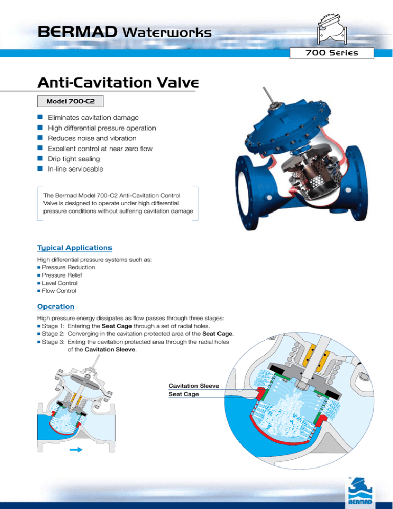
High pressure energy dissipates as flow passes through three stages:
n Stage 1: Entering the Seat Cage through a set of radial holes.
n Stage 2: Converging in the cavitation protected area of the Seat Cage.
n Stage 3: Exiting the cavitation protected area through the radial holes of the Cavitation Sleeve.
Cavitation Sleeve
Seat Cage
BERMAD Waterworks
700 Series
Model 700-C2 Anti Cavitation Valve
Technical Data
Pressure Ratings According to Body Materials
Patterns, End Connections & Sizes
“Y” Pattern: Flanged - 2”-24”; DN50-600
Grooved - 3”-8”; DN80-200,
Threaded - 1½”-3” ; DN40-80
Angle: Flanged - 2”-18” ; DN50-450,
Threaded - 2”-3” ; DN50-80
Max.
Type Operating
Pressure
PN16 16 bar
Flanged ISO 7005-2
PN25 25 bar
ASTM A536
Ductile Iron
= EN 1563
PN25 25 bar
Grooved
Threaded ISO 7/1-RP (BSP) PN25 25 bar
PN16 16 bar
ASTM A216-WCB
Flanged ISO 7005-2
Cast Steel
= EN 10083-1
PN25 25 bar
PN16 16 bar
ASTM A351 CF8M
Stainless
Flanged ISO 7005-2
Steel 316 = EN 10088-1
PN25 25 bar
Body
Material
End Connection
Standard
Grade
Standard Materials:
Main valve body and cover:
Ductile Iron, Carbon Steel, Stainless Steel
Seat Cage & Cavitation Sleeve:
Stainless Steel 304 or 316 (optional)
Main valve internal parts:
Stainless Steel, Bronze & Epoxy coated steel
Other end connection standards available on request.
Elastomers: Synthetic Rubber
Coating: Fusion Bonded Epoxy NSF-61 approved
Other materials are readily available
Water Temperature: Up to 80˚C
Consult factory for higher temperature.
Flow Properties
Size
700-C2
Y-Pattern
700-C2
Angle
mm
Inch
Kv
K
Leq m
Kv
K
Leq m
40
1½"
16
16
32
17
13
26
50
2"
20
24
68
22
20
56
65
2½"
21
66
230
23
55
190
80
3"
43
35
150
47
29
124
100
4"
75
28
167
83
23
138
150
6"
170
27
282
187
23
233
200
8"
300
28
403
330
23
333
250
10"
410
36
661
451
30
546
300 350 400 450
12" 14" 16" 18"
742 744 1,237 1,282
23
42
26
39
537 1,089 768 1,396
816 818 1,361 1,410
19
35
22
32
444 900 634 1,153
500
20"
1,327
56
2,214
N/A
N/A
N/A
600
24”
1,597
80
3,807
N/A
N/A
N/A
Differential Pressure Calculation
Gf
Valve flow coefficient Kv = Q
ΔP
Where:
Kv =Valve flow coefficient (flow in m3/h at 1bar ∆P)
Q =Flow rate (m3/h)
∆P=Differential pressure (bar)
Gf = Liquid specific gravity (Water = 1.0)
2g
Flow resistance or Head loss coefficient K = ΔH 2
V
Where:
K =Flow resistance or Head loss coefficient (dimensionless)
∆H=Head loss (m)
V =Nominal size flow velocity (m/sec)
g =Acceleration of gravity (9.81 m/sec2)
Practical formulas for water:
Practical formula:
V2
ΔH = K
2g
Q = Kv
ΔP
ΔP =
Q
(Kv
)
2
Equivalent Pipe Length - Leq
In order to simplify system head loss calculation, add the Leq value to the pipe length of the relevant size.
Note:
The Leq values given are for general consideration only. Actual Leq may vary somewhat with each of the valve sizes.
BERMAD Waterworks
700 Series
Model 700-C2 Anti Cavitation Valve
Cavitation Charts
1. Calculate the flow velocity in m/sec according to the required flow
and the estimated valve diameter. Use the formula:
V = Flow velocity (m/sec)
Q= Flow (m3/h)
D= Valve diameter (mm)
V = 354 x Q2
D
15
2. Select the relevant chart according to flow velocity
3. Locate cavitation status according to the relevant upstream
and downstream pressure
4. In order to reduce cavitation damage:
n Increase valve size
n Consider multi stage system
n Use higher grade materials - consult Bermad
5. The charts refer to 700-C2 series valves with double cavitation
cages, Ductile Iron bodies and maximum water temperature at 18°C
Downstream Pressure - bar
10
Low
n
atio
avit
C
Mild
5
Downstream Pressure - bar
Downstream Pressure - bar
10
n
tio
vita
Ca
erate
Mod
ation
Cavit
Severe Cavitation
0
0.5
5
10
15
20
Severe Cavitation
5
10
15
Upstream Pressure - bar
erate
Mod
5
10
15
1
Pressure Loss - bar
0.5
250
100
150
200
400
350
300
450
500
600
0.1
0.05
1
10
100
Flow Rate - m3/h
ation
Cavit
Severe Cavitation
Upstream Pressure - bar
80
n
5
Flow Chart
65
n
atio
avit
C
Mild
10
25
25
atio
avit
C
Low
0
0.5
50
20
Flow Velocity = 5 m/sec
Upstream Pressure - bar
40
tion
e Cavita
Moderat
15
w
Lo
on
Mild C
0
0.5
Flow Velocity = 3 m/sec
n
itatio
Cav
avitati
5
6. For project specific cavitation data, please contact Bermad,
with the design parameters of your application.
15
Flow Velocity = 1.5 m/sec
1,000
10,000
20
25
BERMAD Waterworks
700 Series
Model 700-C2 Anti Cavitation Valve
Dimensions & Weights
BSP
BSP
ISO PN 20; 25
ISO PN 10; 16
ISO PN 20; 25 ISO PN 10; 16
DN 40 50 65
Inch 1½” 2” 2½”
L (mm)
N/A 210 222
700-C2
“Y” Pattern
W (mm)
N/A 165 178
h (mm)
N/A 83 95
H (mm)
N/A 244 257
Weight (Kg) N/A 11.1 13.5
L (mm)
N/A 210 222
W (mm)
N/A 165 185
h (mm)
N/A 83 95
H (mm)
N/A 244 257
Weight (Kg) N/A 12.7 15.5
L (mm)
N/A 124 149
700-C2
Angle Pattern
W (mm)
N/A 155 178
R (mm)
N/A 83 95
h (mm)
N/A 85 109
H (mm)
N/A 227 251
Weight (Kg) N/A 10.5 12.5
L (mm)
N/A 124 149
W (mm)
N/A 165 185
R (mm)
N/A 85 95
h (mm)
N/A 85 109
H (mm)
N/A 227 251
Weight (Kg) N/A 12 14
L (mm)
155 155 212
700-C2
“Y” Pattern
W (mm)
122 122 122
h (mm)
40 40 48
H (mm)
201 202 209
Weight (Kg) 6
6
8.5
L (mm)
N/A 121 140
700-C2
Angle Pattern
W (mm)
N/A 122 122
R (mm)
N/A 40 48
h (mm)
N/A 83 102
H (mm)
N/A 225 242
Weight (Kg) N/A 6
7.5
A (mm)
200 200 200
Pilot system and minimum
service distance
B (mm)
350 350 350
Body ports
C
1/4” NPT
1/4”
1/4”
1/4”
Cover ports
D (NPT)
1/8”
1/8”
1/8”
Lower chamber ports
E (NPT)
1
1
Internal single chamber ports F (NPT)
/8”
/8” 1/8”
Control chamber displacement volume (liter)
0.125 0.125 0.125
Stem travel
(mm)
15 15 15
80
3”
250
200
100
305
23
264
207
105
314
26
152
200
100
102
281
22.5
159
207
105
109
287
24
250
163
56
264
18
159
163
55
115
294
16
250
370
1/4”
1/8”
1/8”
0.3
21
100
4”
320
223
115
366
39
335
250
127
378
45
190
222
115
127
342
37
200
250
127
135
350
43
150
6”
415
320
143
492
79
433
320
159
508
89
225
320
143
152
441
75
234
320
159
165
454
85
200
8”
500
390
172
584
133
524
390
191
602
154
265
390
172
203
545
126
277
390
191
216
558
146
A
250
10”
605
480
204
724
232
637
480
223
742
260
320
480
204
219
633
220
336
480
223
236
649
248
D
E
F
H
C
300
12”
725
550
242
840
392
762
550
261
859
432
396
550
248
273
777
372
415
550
261
294
796
412
350
14”
733
550
268
866
403
767
570
295
893
456
400
550
264
279
781
392
419
550
293
299
801
447
400
16”
990
740
300
1,108
896
1,024
740
325
1,133
950
450
740
299
369
1,082
850
467
740
325
386
1,099
905
450
18”
1,000
740
319
1,127
995
1,030
740
357
1,165
1,017
450
740
320
370
1,082
870
467
740
358
386
1,099
920
500
20”
1,100
740
358
1,167
1,012
1,136
750
389
1,197
1,036
N/A
N/A
N/A
N/A
N/A
N/A
N/A
N/A
N/A
N/A
N/A
N/A
A
D
E
H F
C
600
24”
1,450
845
435
1,235
1,123
N/A
N/A
N/A
N/A
N/A
N/A
N/A
N/A
N/A
N/A
N/A
N/A
N/A
N/A
N/A
N/A
N/A
h
h
L
R
B
W
B
320 420 530 620 790 790
400 430 480 520 550 550
3/8” NPT
1/2” NPT
1/4”
1/4”
1/4”
1/2”
1/2”
1/2”
1/8”
1/4”
1/4”
3/8”
3/8”
3/8”
1/8”
1/4”
1/4”
3/8”
3/8”
3/8”
0.45 2.15 4.5 8.5 12.4 12.4
26 35 45 53 72 72
Note: For grooved valves dimensions, refer to flanged valves dimensions
info@bermad.com • www.bermad.com
The information herein is subject to change without notice. BERMAD shall not be held liable for
PC7WE11C2 11
any errors. All rights reserved. © Copyright by BERMAD.
L
B
B
W
B
1000 1000 1000
650 650 650
1” BSPT
3/4”
3/4”
3/4”
3/4”
3/4”
3/4”
3/4”
3/4”
3/4”
29.8 29.8 29.8
100 100 100
1000
650
3/4”
3/4”
3/4”
29.8
100


