Spec Sheet
advertisement
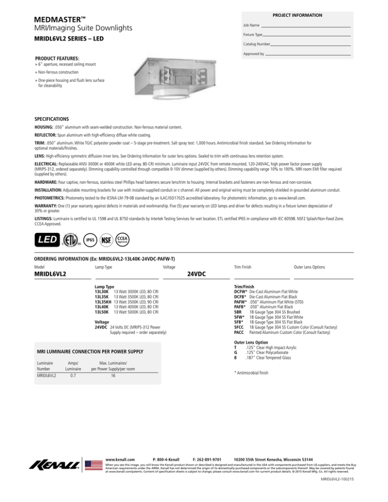
PROJECT INFORMATION MEDMASTER™ MRI/Imaging Suite Downlights Job Name Fixture Type MRIDL6VL2 SERIES – LED Catalog Number Approved by PRODUCT FEATURES: »» 6" aperture, recessed ceiling mount »» Non-ferrous construction »» One-piece housing and flush lens surface for cleanability SPECIFICATIONS HOUSING: .050" aluminum with seam-welded construction. Non-ferrous material content. REFLECTOR: Spun aluminum with high-efficiency diffuse white coating. TRIM: .050" aluminum. White TGIC polyester powder coat – 5-stage pre-treatment. Salt spray test: 1,000 hours. Antimicrobial finish standard. See Ordering Information for optional materials/finishes. LENS: High-efficiency symmetric diffusion inner lens. See Ordering Information for outer lens options. Sealed to trim with continuous lens retention system. ELECTRICAL: Replaceable ANSI 3000K or 4000K white LED array. 80 CRI minimum. Luminaire input 24VDC from remote-mounted, 120-240VAC, high power factor power supply (MRIPS-312, ordered separately). Dimming capability controlled through compatible 0-10V dimmer (supplied by others). Dimming capability range 10% to 100%. MRI room EMI filter required (supplied by others). HARDWARE: Four captive, non-ferrous, stainless steel Phillips head fasteners secure lens/trim to housing. Internal brackets and fasteners are non-ferrous and non-corrosive. INSTALLATION: Adjustable mounting brackets for use with installer-supplied conduit or c-channel. All power and original wiring must be completely shielded in grounded aluminum conduit. PHOTOMETRICS: Photometry tested to the IESNA LM-79-08 standard by an ILAC/ISO17025 accredited laboratory. For photometric information, go to www.kenall.com. WARRANTY: One (1) year warranty against defects in materials and workmanship. Five (5) year warranty on LED lamps and driver for defects resulting in a fixture lumen depreciation of 30% or greater. LISTINGS: Luminaire is certified to UL 1598 and UL 8750 standards by Intertek Testing Services for wet location. ETL certified IP65 in compliance with IEC 60598. NSF2 Splash/Non-Food Zone. CCEA Approved. LED CCEA IP65 Approved ORDERING INFORMATION (Ex: MRIDL6VL2-13L40K-24VDC-PAFW-T) Model Lamp Type Voltage MRIDL6VL2 Trim Finish Outer Lens Options 24VDC Trim/Finish DCFW* Die-Cast Aluminum Flat White DCFB* Die-Cast Aluminum Flat Black PAFW* .050" Aluminum Flat White (STD) PAFB* .050" Aluminum Flat Black 5BR 18 Gauge Type 304 SS Brushed 5FW* 18 Gauge Type 304 SS Flat White 5FB* 18 Gauge Type 304 SS Flat Black 5FCC 18 Gauge Type 304 SS Custom Color (Consult Factory) PACC Painted Aluminum Custom Color (Consult Factory) Lamp Type 13L30K 13 Watt 3000K LED, 80 CRI 13L35K 13 Watt 3500K LED, 80 CRI 13L35KH 13 Watt 3500K LED, 90 CRI 13L40K 13 Watt 4000K LED, 80 CRI 13L50K 13 Watt 5000K LED, 80 CRI Voltage 24VDC24 Volts DC (MRIPS-312 Power Supply required – order separately) Outer Lens Option T .125" Clear High Impact Acrylic G .125" Clear Polycarbonate 8 .187" Clear Tempered Glass MRI LUMINAIRE CONNECTION PER POWER SUPPLY Luminaire Amps/ Max. Luminaires/ Number Luminaire per Power Supply/per room MRIDL6VL20.7 16 www.kenall.com * Antimicrobial finish P: 800-4-Kenall F: 262-891-9701 10200 55th Street Kenosha, Wisconsin 53144 When you see this image, you will know the Kenall product shown or described is designed and manufactured in the USA with components purchased from US suppliers, and meets the Buy American requirements under the ARRA. Kenall has not determined the origin of its domestically purchased components or the subcomponents thereof. May be covered by patents found at www.kenall.com/patents. Content of specification sheets is subject to change; please consult www.kenall.com for current product details. © 2015 Kenall Mfg. Co. All rights reserved. MRIDL6VL2-100215 For additional photometry, go to www.kenall.com MEDMASTER™ MRI/Imaging Suite Downlights MRIDL6VL2 SERIES – LED Initial Delivered Lumens @ 25°C Lamp Type Type T Type 8 Type 9 Efficacy (lm/W) Input Power (W) Drive Current (mA) Estd. L70 LED Life (Hrs) Lumen Maintenance @50K 13L30K 1,043 940 978 59 - 65 16 117 125,000 89% 13L35K 1,189 1,072 1,115 67 - 74 16 117 125,000 89% 13L35KH 945 852 886 53 - 59 16 117 125,000 89% 13L40K 1,189 1,072 1,115 67 - 74 16 117 125,000 89% 13L50K 1,189 1,072 1,115 67 - 74 16 117 125,000 89% Displayed information above is for selected luminaires only. Additional wattages and color temperatures are also available. Visit www.kenall.com for additional information. Model: MRIDL6VL2-13L35K-DV-2FW-T Model: MRIDL6VL2-13L35K-DV-2FW-G Model: MRIDL6VL2-13L35K-DV-2FW-8 555 520 500 416 390 375 278 260 250 139 130 125 2 2 2 1 1 1 Max Candela = 555 Located At Horizontal Angle = 0, Vertical Angle = 0 Max Candela = 520 Located At Horizontal Angle = 0, Vertical Angle = 0 Max Candela = 500 Located At Horizontal Angle = 0, Vertical Angle = 0 1 - Vertical Plane Through Horizontal Angles (0-180) (Through Max. Cd.) 2 - Horizontal Cone Through Vertical Angle (0) (Through Max. Cd.) 1 - Vertical Plane Through Horizontal Angles (0-180) (Through Max. Cd.) 2 - Horizontal Cone Through Vertical Angle (0) (Through Max. Cd.) 1 - Vertical Plane Through Horizontal Angles (0-180) (Through Max. Cd.) 2 - Horizontal Cone Through Vertical Angle (0) (Through Max. Cd.) DIMENSIONAL DATA CROSS SECTION BOTTOM VIEW 18.19" 14.19" 5.25" 6.375" Aperture 1.375" Max Ceiling 21.48" 8.63" Recommended Ceiling Cutout: 8.125" Diameter www.kenall.com P: 800-4-Kenall F: 262-891-9701 10200 55th Street Kenosha, Wisconsin 53144 When you see this image, you will know the Kenall product shown or described is designed and manufactured in the USA with components purchased from US suppliers, and meets the Buy American requirements under the ARRA. Kenall has not determined the origin of its domestically purchased components or the subcomponents thereof. May be covered by patents found at www.kenall.com/patents. Content of specification sheets is subject to change; please consult www.kenall.com for current product details. © 2015 Kenall Mfg. Co. All rights reserved. MRIDL6VL2-100215 MEDMASTER™ DOWNLIGHT MRIDL6VL2 LED SERIES INSTALLATION INSTRUCTIONS 1 IMPORTANT SAFEGUARDS When using electrical equipment, basic safety precautions should always be followed, including the following: TO PREVENT MRI MACHINE INTERFERENCE, ALL DC POWER AND DIMMING SIGNAL WIRING MUST BE COMPLETELY SHIELDED WITHIN GROUNDED ALUMINUM CONDUIT AND A SUITABLE MRI ROOM EMI FILTER MUST BE INSTALLED ON EACH LINE. THIS PRODUCT MUST BE INSTALLED IN ACCORDANCE WITH THE APPLICABLE INSTALLATION CODE BY A PERSON FAMILIAR WITH THE CONSTRUCTION AND OPERATION OF THE PRODUCT AND THE HAZARDS INVOLVED. DISCONNECT POWER TO ALL CIRCUITS BEFORE WIRING FIXTURE. INSTALL IN ACCORDANCE WITH ALL NATIONAL, STATE, AND LOCAL CODES. DO NOT CONNECT TO AN UNGROUNDED SUPPLY. WIRING CONNECTIONS MUST BE MADE INTERNAL TO THE ENCLOSURE. FAILURE TO INSTALL UNIT ON A MECHANICALLY-SOUND SURFACE MAY RESULT IN PERSONAL INJURY, PHYSICAL DAMAGE, OR POTENTIAL FIRE HAZARD. USE INSTALLATION PROCEDURES APPROPRIATE FOR AN ENVIRONMENT INVOLVING MRI AND SENSITIVE ELECTRONIC EQUIPMENT. READ ALL FIXTURE MARKINGS AND LABELS TO ENSURE CORRECT INSTALLATION OF FIXTURE. SUPPLEMENTAL INSTRUCTIONS MAY BE LOCATED ON THE FIXTURE, IN ADDITION TO THIS INSTRUCTION SHEET, REGARDING ORIENTATION, OR MOUNTING RESTRICTIONS. READ INSTRUCTIONS PROVIDED WITH THE MEDMASTER™ MRIPS-312 EXTERNAL POWER SUPPLY FOR PROPER INSTALLATION AND ELECTRICAL CONNECTION TO THE LIGHTING SYSTEM. SAVE THESE INSTRUCTIONS CUSTOMER ACKNOWLEDGMENT CUSTOMER ACKNOWLEDGES THAT THESE INSTALLATION INSTRUCTIONS ARE PART OF THE PRODUCT SPECIFICATION, AND THAT THE ATTACHED INSTALLATION REGISTRATION FORM WILL BE PROVIDED TO THE INSTALLER TO SIGN AND RETURN TO KENALL AFTER INSTALLATION IS COMPLETE. THIS SIGNED RELEASE IS REQUIRED BY KENALL BEFORE ORDER WILL BE RELEASED INTO PRODUCTION Signature: Print Name: Date: Company Name: INSTALLATION INSTRUCTIONS 2 This instruction sheet applies for the Kenall MedMaster™ MRIDL6VL2 DownLight. A separate instruction sheet is provided in the MRIPS-312 external power supply. Both sheets are intended to provide comprehensive instructions on fixture installation and wiring. 3. Bottom of die-cast frame should be flush with room side surface of ceiling panel. See Figure 2. Adjust mounting brackets by loosening four (4) wingnuts (inside fixture) and adjust fixture to correct height. Re-tighten nuts after adjusting. The MedMaster™ MRIDL6VL2 lighting system contains sensitive electronics. Take care to avoid damage by improper handling or static electricity discharge (ESD). Either type of damage could render the system inoperable or cause latent failure. Make sure all hardware and equipment required for installation, but not supplied with the luminaire, is non-ferrous and suitable for installation within an MRI room. I. LUMINAIRE MOUNTING PROCEDURE – DROPIN CEILINGS 1. Cut an 8.125" diameter hole in ceiling panel and install panel. 2. Insert conduit or c-channel (by others) through mounting brackets. Bend brackets to secure. Lift fixture into ceiling through adjacent opening and position over cutout. See Figure 1 below. II. LUMINAIRE MOUNTING PROCEDURE – DRYWALL CEILINGS 4. Insert conduit or c-channel (by others) through mounting brackets. Bend brackets to secure. 5. Mount fixture in ceiling so that the weight of the fixture is supported by framing material and/or hanger wires secured to the building structure. www. kenall.com P: 800-4-Kenall F: 847-360-1781 1020 Lakeside Drive Gurnee, Illinois 60031 INSTALLATION INSTRUCTIONS 3 6. Bottom of diecast frame should be flush with room side of ceiling surface (figure 4). Adjust mounting brackets by loosening (4) wingnuts (inside fixture) and adjust fixture to correct height. Re-tighten wingnuts after adjusting. III. ELECTRICAL CONNECTION 7. Mount and wire the MRIPS-312 external power supply per the procedures provided in the supplementary instruction sheet. Run conduit and DC wiring to an MRI room EMI filter sized to the load of the power supply (supplied by others). Make sure wiring is completely enclosed in grounded aluminum conduit. Any gaps, regardless of size, must be closed or wrapped in copper foil tape. 8. If a 0-10V dimmer is to be connected, install at this time. Dimmer must be installed outside the shielded MRI environment with an intermediate MRI room EMI filter to the luminaires. Kenall recommends using a Leviton® lllumaTech™ IP710 series dimmer or Grafik Eye GRX-TVI control interface. Contact Kenall for suitability of using an alternate sink-type 0-10V dimmer. 9. After the luminaires are mounted and secured, access the external junction box to gain access to supply connections. Each wire is labeled and color coded for easy identification. The junction box cover is located on the side of the luminaire housing. www. kenall.com P: 800-4-Kenall F: 847-360-1781 1020 Lakeside Drive Gurnee, Illinois 60031 INSTALLATION INSTRUCTIONS 4 10. required. Make sure wiring is completely enclosed in grounded aluminum conduit. Any gaps, regardless of size, must be closed or wrapped in copper foil tape. Special attention should be paid to the wiring entry point into the shielded space. See Figure 5. 11. wires. Make sure wiring is completely enclosed in grounded aluminum conduit. Any gaps, regardless of size, must be closed or wrapped in copper foil tape. Special attention should be paid to the wiring entry point into the shielded space. See Figure 5. 12. Make DC supply and (optional) dimmer control connections within each luminaire. Cap gray and violet leads if dimmer is not connected. 13. Using at least an 18 AWG wire, ground the last housing in the sequence to the shielded ceiling. This can be done by fastening the wire to one of the luminaire’s junction box screws. 14. Reinstall all provided bracketry and internal enclosures provided with the luminaire. These parts are critical to the overall EMI shielding of the system. 15. Connect power to external power supply and test for proper operation of lighting system. Make sure all LEDs are lit and dimming operation works as intended (if connected). 16. Test operation of lighting during MRI machine idle mode and during scanning operations. 17. Fill out the Installation Registration Form (attached to MRIPS-312 instruction sheet) and fax to Kenall at (847) 360-1781. OUTSIDE MRI ROOM + NEUTRAL 24V _ 120VAC 50/60 INSIDE MRI ROOM + RF FILTER _ RED BLACK PURPLE GRAY Luminaire 1 SW HOT RED PURPLE BLACK RED BLACK GRAY 0-10V Dimmer Luminaire 2 RF FILTER (Leviton IP710) RED (Lutron NTSTV) BLACK Luminaire N (last) GRAY PURPLE Figure 5- MRI Luminaire Installation Wiring Diagram NOTE: 24VDC and Dimming Wires to be run through same conduit. INSTALLATION INSTRUCTIONS 5 RECOMMENDED LAYOUT NOT RECOMMENDED 0-10V 24 VDC LUMINAIRE LUMINAIRE LUMINAIRE 0-10V LUMINAIRE LUMINAIRE LUMINAIRE 24 VDC LUMINAIRE LUMINAIRE LUMINAIRE LUMINAIRE LUMINAIRE LUMINAIRE LUMINAIRE LUMINAIRE LUMINAIRE LUMINAIRE LUMINAIRE LUMINAIRE POWER LINE CONDUIT DIMMING LINE CONDUIT IV. CONCLUSION OF LUMINAIRE MOUNTING PROCEDURE 18. Install trim (shipped separately) into frame opening. Attach trim to frame using (4) captive fasteners. www. kenall.com P: 800-4-Kenall F: 847-360-1781 1020 Lakeside Drive Gurnee, Illinois 60031 INSTALLATION INSTRUCTIONS 6 CUSTOMER SERVICE For technical assistance, call 1-800-4KENALL (1-800-453-6255). WARRANTY This product is warranted by Kenall to be free of defects in workmanship and materials for a period of one (1) year from the date of the invoice. LED lamps and internal power regulation components are warranted for a period of five (5) years from the date of the invoice against defects in materials and workmanship. The external DC power supply carries a three year warranty from the date of the invoice. The warranty is void if all power and dimming signal wiring is not completely shielded against grounded aluminum conduit and installed with a suitable MRI room filter (by others). Kenall reserves the right to issue credit, repair, or replace the defective merchandise, at its discretion, upon notification and confirmation by its local representative of the defect. Kenall also reserves the right to test and examine the defective product if the defect is questionable and to deny the warranty herein for any product altered, improperly installed, installed in applications for which it is not intended. This includes operation in ambient temperatures above stated limits for any length of time. Failure by electrical surge shall not be covered under warranty. Kenall assumes no responsibility for labor or freight costs incurred in connection with the installation, removal, or replacement of products determined to be defective or any other consequential or incidental damages arising from the use of the product. Kenall’s entire liability on any claim of loss or damage resulting from a defective product is limited to the replacement price of the product. The foregoing warranty is exclusive of all other warranties and no other warranties of any kind are expressed or implied. INSTALLATION INSTRUCTIONS 7 CUSTOMER ACKNOWLEDGEMENT MRI INSTALLATION REGISTRATION FORM Customer acknowledges that the attached Installation Registration Form will be provided to the installer to sign and return to Kenall afterinstallation is complete. For warranty purposes, please fill out this form and return to Kenall by fax at (847) 360-1781. I certify that the lighting installation for the listed MRI suite location is completed per the provided installation instructions and to the best of my abilities. Please check off items to denote status: Installation instruction sheets for MRIPS-312 power supply and individual luminaire(s) read and followed. MRIPS-312 power supply and EMI filters are located outside the shielded enclosure. All DC supply wiring is completely enclosed within grounded aluminum conduit. Installation has no ungrounded/unshielded portions of conduit or openings of any size or shape. All dimming signal wiring is completely enclosed within grounded aluminum conduit. Installation has no ungrounded/unshielded portions of conduit or openings of any size or shape. Check here if dimming is not applicable: MRI Room EMI filters for the 24VDC supply are of the type intended for MRI suites and are sized to the electrical load. DC supply power and dimming signal are NOT running through the same EMI filter. Check here if dimming is not applicable: Lighting system fully tested (including dimming operation, if applicable) while MRI machine is in idle and scan operation mode. If any of these steps cannot be completed or you need technical assistance, please contact Kenall Technical Support at 1-800-4KENALL (1-800-453-6255). Electrical Contractor Installation Site Name: ___________________________________ Name: ___________________________________ City/State: ________________________________ City/State: ________________________________ Phone:___________________________________ FAX FORM TO (847) 360-1781 Installation Date: ___________________________ (Do not write below line) Kenall Received By: ___________________________________ Received Date: ________________________________
