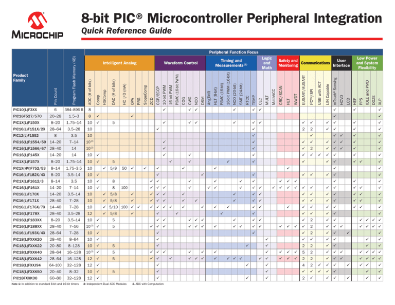
8-bit PIC® Microcontroller Peripheral Integration
Quick Reference Guide
ü
ü ü
ü
ü ü
ü
ü
ü ü
ü
ü ü
ü
ü
ü
ü
ü
ü
ü
2
2
ü
ü
ü
ü
ü ü
ü
ü
ü
5
XLP
ü
ü
ü
DOZE
IDLE and PMD
PPS
HEF
LCD
HCVD
mTouch® Sensing
LIN Capable
USB with ACT
I2C™/SPI
EUSART/AUSART
WWDT
HLT
CRC/SCAN
MathACC
MULT
CLC
10-bit PWM
CCP/ECCP
ZCD
SlopeComp
PRG
OPA
HC I/O (mA)
DAC (# of bits)
HSComp
Comp
Low Power
and System
Flexibility
Safety and
User
Communications
Monitoring
Interface
ü
ü
3.5
10
PIC16(L)F1554/59 14–20
7–14
10 (2)
ü
ü
ü
ü
ü
ü ü
ü
ü
PIC16(L)F1566/67 28–40
14
10 (2)
ü
ü
ü
2
ü
ü ü
ü
ü
ü
ü
ü
ü
ü
ü
ü
ü
ü
ü
ü
ü ü
ü
PIC12(L)F1552
8
TEMP
10
RTCC
3.5–28
SMT (24-bit)
28–64
NCO (20-bit)
PIC16(L)F151X/2X
16-bit PWM (16-bit)
ü
PSMC (16-bit)
10
HLT (8-bit)
1.75–14
AngTMR
8–20
DSM
ü
PIC1X(L)F150X
NCO
8
CWG
8
1.5–3
COG
ADC (# of bits)
384–896 B
20–28
PIC10(L)F3XX
Logic
and
Math
Timing and
Measurements (1)
Waveform Control
PSMC (16-bit PWM)
Program Flash Memory (KB)
6
PIC16F527/570
Product
Family
Intelligent Analog
16-bit PWM
Pin Count
Peripheral Function Focus
ü
PIC16(L)F145X
14–20
14
10
ü
PIC1X(L)F157X
8–20
1.75–14
10
ü
PIC1X(HV)F752/53
8–14
1.75–3.5
10
PIC16(L)F182X/4X
8–20
3.5–14
10
ü
PIC1X(L)F1612/3
8–14
3.5
10
ü
8
PIC16(L)F161X
14–20
7–14
10
ü
8
PIC16(L)F170X
14–20
3.5–14
10
ü
5/8
ü
ü ü ü
ü
PIC16(L)F171X
28–40
7–28
10
ü
5/8
ü
ü ü ü
ü
PIC16(L)F176X/7X
14–40
7–28
10
ü 5/10 100 ü ü
ü ü ü ü
ü
PIC16(L)F178X
28–40
3.5–28
12
ü
PIC16(L)F183XX
8–20
3.5–14
PIC16(L)F188XX
28–40
7–56
10
ü
5
ü
5/9
50
ü
ü
ü
ü
ü
ü
ü
ü
5/8
100
ü
ü
ü
ü ü ü
ü
ü ü
ü
ü ü
ü
5
ü ü
ü ü ü
5
ü ü ü
ü ü ü
28–64
7–28
10
ü
ü
28–40
8–64
10
ü
ü
PIC18(L)FXXK22
20–80
8–128
10
PIC18(L)FXXK40
28–64
16–128
ü
5
ü
10 (3) ü
5
ü ü ü
5
ü ü
28–64
16–128
12
ü
PIC18(L)FXXJ94
64–100
32–128
12
ü
PIC18(L)FXXK50
20–40
8–32
10
ü
PIC18FXXK90
60–80
32–128
12
ü
ü
5
ü
2: Independent Dual ADC Modules 3. ADC with Computation
ü
ü
ü ü
ü
ü
ü
ü
ü ü ü
ü
ü
ü
ü
ü
ü
ü
ü
ü
ü ü
ü
ü
ü
ü
ü
ü ü
ü
ü ü
ü
ü
ü
ü
ü ü
ü
ü
ü
ü
ü
ü ü
ü
ü
ü
ü
ü
ü ü
ü
ü
ü
ü ü
ü ü
ü ü
ü
ü
ü
ü
ü ü
ü
ü
ü
ü ü ü
ü
ü
ü
2
ü
ü
ü ü ü ü
2
ü
ü ü
ü ü ü ü
ü
2
ü
ü
ü
ü
ü
ü
ü
2
2
ü
ü
5
2
ü
ü ü
ü
ü
ü
ü
ü ü
ü
ü
ü
ü
ü
ü
ü
ü
ü
ü
ü
ü
ü
ü
ü
ü
ü
ü
PIC16(L)F193X/4X
ü
ü
10 (3) ü
PIC18(L)FXXK42
ü
ü
ü
ü
ü
ü
ü
ü
ü
ü
ü ü
PIC18(L)FXXK20
Note 1: In addition to standard 8-bit and 16-bit timers
ü
ü
ü
2
2
ü
4
2
ü
ü
ü
ü
ü
ü
2
ü
ü
ü ü
ü
ü
ü
ü
ü
ü
ü
ü
ü
ü
ü
ü
ü ü ü ü
ü ü ü ü
ü
ü ü
ü
ü
ü
ü
ü
ü
Intelligent Analog: Sensor Interfacing and Signal Conditioning
ADC: Analog-to-Digital Converter
General purpose 8-/10-/12-bit ADC
ADC2/ADCC: Analog-to-Digital Converter General purpose 10-/12-bit ADC with automated analog signal analysis
with Computation
(ex. oversampling, averaging, etc.)
Comp: Comparator
General purpose rail-to-rail comparator
DAC: Digital-to-Analog Converter
Programmable voltage reference with multiple internal and external connections
HC I/O: High-Current I/O
Up to 50 mA or 100 mA current drive on select I/O pins
HSComp: High-Speed Comparator
General purpose rail-to-rail comparator with < 50 ns response time
OPA: Operational Amplifier
General purpose op amp for internal and external signal source conditioning
Analog ramp generator (with slope compensation) for current/voltage mode
PRG: Programmable Ramp Generator
power supplies
SlopeComp: Slope Compensation
Slope compensation for Peak Current Mode power supplies
Stable fixed voltage reference for use with integrated analog peripherals
VREF: Voltage Reference
AC high-voltage zero-crossing detection for simplifying TRIAC control,
ZCD: Zero Cross Detect
synchronized switching control and timing
waveform Control: PWM Drive and Waveform Generation
CCP/ECCP: 1. CCP/ECCP: 10-bit PWM control with 16-bit capture and compare
(Enhanced) Capture Compare PWM
2. ECCP: Addition of auto shutdown control
Automated complementary output with control of key parameters such as
COG: programmable rising/falling edge events, polarity, phase, precision
Complementary Output Generator
dead-band, blanking and auto shutdown
CWG: Automated complementary output with control of key parameters such as
Complementary Waveform Generator
dead-band and auto shutdown
1. Modulates up to two carrier signals with digital data to create custom
carrier synchronized output waveforms
DSM: Data Signal Modulator
2. LED dimming engine functionality via interconnection with 10-/16-bit
PWM, DSM and op amp
1. Precision linear frequency generator (@ 50% duty cycle) with 0.0001%
NCO: Numerically Controlled Oscillator
step size of source input clock frequency
and 16-/20-bit Timer/Counter
2. General purpose 16-/20-bit timer/counter
1. 16-bit PWM with dedicated 64 MHz clock source and event triggering
2. Automated complementary output with control of key parameters such
PSMC: Programmable Switch Mode
as programmable rising/falling edge events, polarity, phase, precision deadController and 16-bit Timer/Counter
band, blanking and auto shutdown
3. General purpose 16-bit timer/counter
PWM: Pulse Width Modulation
General purpose 10-bit PWM control
16-bit PWM: Standalone 16-bit PWM
1. High-resolution 16-bit PWM with edge- and center-aligned modes
and 16-bit Timer/Counter
2. General purpose 16-bit timer/counter
Timing and Measurements: Signal Measurement with Timing and Counter Control
Phase angle timer for measurement and control of rotational and periodic
AngTMR: Angular Timer
events (ex. motor, AC mains, TRIAC, etc.)
CTMU: Time measurement unit that provides method for temperature sensing, time
Charge Time Measurement Unit
measurements (down to 1 ns) and mTouch® sensing
HLT: Hardware Limit Timer and 8-bit
1. Hardware monitoring for missed periodic events and fault detection
Timer/Counter
2. General purpose 8-bit timer/counter with external reset capabilities
1. Precision linear frequency generator (@ 50% duty cycle) with 0.0001%
NCO: Numerically Controller Oscillator
step size of source input clock frequency
and 16-/20-bit Timer/Counter
2. General purpose 16-/20-bit timer/counter
1. 16-bit PWM with dedicated 64 MHz clock source and event triggering
2. Automated complementary output with control of key parameters such as
PSMC: Programmable Switch Mode
programmable rising/falling edge events, polarity, phase, precision
Controller and 16-bit Timer/Counter
dead-band, blanking and auto shutdown
3. General purpose 16-bit timer/counter
RTCC: Real-Time Clock/Calendar
Maintains accurate clock and calendar timing with external 32.768 kHz crystal
1. Accurate measurement of any digital signal including period, duty cycle,
SMT: 24-bit Signal Measurement
time of flight; instantaneous vs. average measurements
Timer and 24-bit Timer/Counter
2. General purpose 24-bit timer/counter
TEMP: Temperature Indicator
Provides relative temperature measurements utilizing the ADC
8-/16-bit Timer
General purpose 8-/16-bit timer/counter
16-bit PWM: Standalone 16-bit PWM
1. High-resolution 16-bit PWM with edge- and center-aligned modes
and 16-bit Timer/Counter
2. General purpose 16-bit timer/counter
Logic and Math: Customizable Logic and Math Functions
1. Integrated combinational and sequential logic
CLC: Configurable Logic Cell
2. Customer interconnection and re-routing of digital peripherals
MULT: Hardware Multiplier
MULTIPLY function of two 8-bit values with 16-bit result
1. MULTIPLY, ADD, ACCUMULATE functions of 8-/16-bit values with 35-bit result
2. Calculates a 16-bit PID function based on configurable Kp, Ki, Kd
MathACC: Math Accelerator
constants with a 34-bit result
Safety and Monitoring: Hardware Monitoring and Fault Detection
1. Automatically calculates CRC checksum of Program/DataEE memory for
CRC/SCAN: NVM integrity
Cyclical Redundancy Check
2. General purpose 16-bit CRC for use with memory and communications data
with Memory Scan
HLT: 1. Hardware monitoring for missed periodic events and fault detection of
Hardware Limit Timer and 8-bit
external hardware
Timer/Counter
2. General purpose 8-bit timer/counter with external reset capabilities
System supervisory circuit that generates a reset when software timing
WWDT: Windowed Watch Dog Timer
anomalies are detected within a configurable critical window
Communications: General, Industrial, Lighting and Automotive
1. Auto-tuning of internal oscillator when connected to USB host (eliminates
ACT: need for external crystal)
Active Clock Tuning for Crystal-Free USB
2. Tunes internal oscillator to match accuracy of external clock source
CAN: Controller Area Network
Industrial- and automotive-centric communcation bus
1. Industrial- and automotive-centric communication bus
LIN: Local Interconnect Network
2. Support for LIN when using the EUSART
EUSART/AUSART: 1. General purpose serial communications
Enhanced/Addressable Universal
2. Support for LIN when using the EUSART
Asynchronous Receiver Transceiver
General purpose 2-wire serial communications
I2C™: Inter-Integrated Circuit
SPI: Serial Peripheral Interface
General purpose 4-wire serial communications
USB: Universal Serial Bus
Support for full-speed USB 2.0 device profiles
User Interface: Capacitive Touch Sensing and LCD Control
HCVD: Simplifies implementation and reduces overhead of
Hardware Capacitive Voltage Divider
mTouch sensing applications
LCD: Liquid Crystal Display
Highly integrated segmented LCD controller
1. Capacitive sensing for touch buttons and sliders
mTouch: Microchip Proprietary
2. Capacitive sensing for system measurements and detection (ex. water
Capacitive Touch Technology
level, intrusion detection, etc.)
Low Power and System Flexibility: XLP Low-Power Technology, Peripheral and Interconnects
Ability to run the CPU core slower than the system clock used by the
DOZE: Power Saving Mode
internal peripherals
HEF: High-Endurance Flash
128B Non-volatile data storage with high-endurance 100k E/W cycles
Ability to put the CPU core to sleep while the internal peripherals continue
IDLE: Power Saving Mode
to operate from the system clock
Peripheral power disable hardware to minimze power consumption of
PMD: Peripheral Module Disable
unused peripherals
I/O pin remapping of digital peripherals for greater design flexibility and
PPS: Peripheral Pin Select
improved EMI board layout
Industry-leading low-power technology (LF variants only, unless
XLP: eXtreme Low Power Technology
otherwise noted)
PDF version available for download at www.microchip.com/8bitquickreference.
Learn more about 8-bit PIC Microcontrollers
at www.microchip.com/8bit.
Learn more about Core Independent
Peripherals (CIP) at www.microchip.com/CIP.
Information subject to change. The Microchip name and logo, the Microchip logo, KeeLoq, mTouch and PIC are registered trademarks of Microchip Technology Incorporated in the U.S.A. and other countries. © 2015, Microchip Technology Inc.
All Rights Reserved. Printed in the U.S.A. 5/15. DS30010068C


