VG Series
LED Parking Luminaire
Junction Box Mount
IMPORTANT SAFEGUARDS
INSTALLATION INSTRUCTIONS
When using electrical equipment, basic safety precautions should always be followed
including the following:
READ AND FOLLOW ALL SAFETY
INSTRUCTIONS
1.
To reduce the risk of electrical shock, turn off power supply before installation or
servicing.
This luminaire must be installed in accordance with the NEC or your local
electrical code. If you are not familiar with these codes and requirements, consult
a qualified electrician.
DO NOT lift luminaire by the power leads.
DO NOT carry or lift luminaire by wireform. Wireform is only for supporting
luminaire while making wiring connections.
2.
3.
4.
SAVE THESE INSTRUCTIONS FOR FUTURE
REFERENCE
TO INSTALL:
LUMINAIRE INSTALLATION
2
1
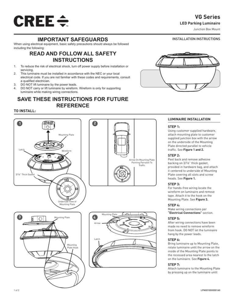
STEP 1:
Using customer supplied hardware,
attach mounting plate to customer
supplied junction box with the arrow
on the underside of the Mounting
Plate directed parallel to vehicle
traffic. See Figure 1 and 2.
Mounting Plate
Latch
Wireform
STEP 2:
Arrow On Mounting Plate
Pointing Parrallel To
Traffic
3/16” Thick Gasket
Peel back and remove adhesive
backing on 3/16” thick gasket,
provided in hardware bag, and attach
it centered to underside of Mounting
Plate covering all slots and screw
heads. See Figure 1.
STEP 3:
For hands-free wiring locate the
wireform on luminaire and remove
tape. Attach it to the hook on the
Mounting Plate. See Figure 3.
Underside View of
Mounting Plate
3
Mounting Plate
Mounting
Plate Hook
STEP 4:
4
Mounting Plate
Make wiring connections per
“Electrical Connections” section.
STEP 5:
Arrow
After wiring connections have been
made no need to remove wireform
from hook. DO NOT let the luminaire
hang by the power leads.
Latch
STEP 6:
Bring luminaire up to Mounting Plate,
rotate luminaire until the arrow on the
inside of the Mounting Plate points to
the recessed area nearest to the latch
on the luminaire. See Figure 4.
STEP 7:
Attach luminaire to the Mounting Plate
by pressing up on the luminaire until
1 of 2
LPN00100X0001A0
5
Slots
Slots
Mounting
Plate
the slots on the Mounting Plate engage with the clips on the
luminaire and rotate until latch locks securely. See Figure
5.
NOTE: May require extra pressure on luminaire to engage
clips into Mounting Plate slots.
NOTE: If the Mounting Plate slots become deformed during
installation, slightly reopen the slots back up using a
screwdriver to ensure proper install of luminaire.
STEP 8:
Lightly pull on the luminaire to verify luminaire is securely
mounted.
FIXTURE SERVICING AND MAINTENANCE
Tamerproof
screw
Luminaire
Clips
STEP 1:
If supply wiring splices need to be inspected or if luminaire
needs to be removed, fully loosen the tamperproof screw
and slide out the latch. Then, rotate luminaire to disengage
from Mounting Plate. See Figure 5.
STEP 2:
To re-install luminaire, when finished with servicing or
maintenance, engage and tighten the latch’s tamperproof
screw and follow Step 1-7 in “Luminaire Installation”
section above.
ELECTRICAL CONNECTIONS
STEP 1:
Make the following Electrical Connections :
a. For 120/277V connect the black fixture lead to the voltage
supply position of the junction box (Hot 1 for 208/240V
wiring).
b. For 120/277V Connect the white fixture lead to the neutral
supply position of the junction box (Hot 2 for 208/240V
wiring).
c. Connect the green or green/yellow ground lead to the green
wire position of the junction box.
d. If Dimming is an option; connect the violet dimming positive
lead to the supply dimming positive lead.
e. If Dimming is an option; connect the grey dimming negative
lead to the supply dimming negative lead.
© 2015 Cree, Inc. All rights reserved. For informational purposes only. Content is subject to change.
See www.cree.com/canada for warranty and specifications. Cree® is a registered trademark, and the Cree logo is a
trademark of Cree, Inc.
www.cree.com/canada
2 of 2
LPN00100X0001A0


