- Bastl Instruments
advertisement

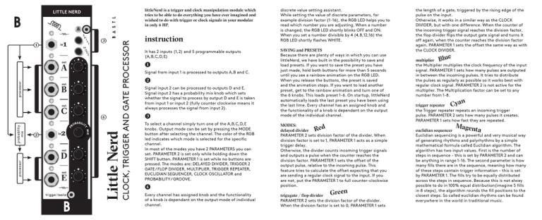
littleNerd is a trigger and clock manipulation module which tries to be able to do everything you have ever imagined and wished to do with trigger or clock signals in your modular in only 6 HP. ) M O D E processor ) ) Little Nerd processor probability mix ) CLOCK, TRIGGER AND GATE PROCESSOR LITTLE NERD instruction It has 2 inputs (1,2) and 5 programmable outputs (A,B,C,D,E) ) Signal from input 1 is processed to outputs A,B and C. ) Signal input 2 can be processed to outputs D and E. Signal input 2 has a probability mix knob which sets whether the signal to process by output D and E is taken from input 1 or input 2 (fully counter clockwise means it always processes the signal from input 2). ) To select a channel simply turn one of the A,B,C,D,E knobs. Output mode can be set by pressing the MODE button after selecting the channel. The color of the RGB led indicates which mode is selected for the specific channel. In most of the modes you have 2 PARAMETERS you can set. PARAMETER 2 is set only while holding down the SHIFT button. PARAMETER 1 is set while no buttons are pressed. The modes are: DELAYED DIVIDER, TRIGGER 2 GATE / FLOP DIVIDER, MULTIPLIER, TRIGGER REPEATER, EUCLIDIAN SEQUENCER, CLOCK OSCILLATOR and PROBABILITY / GROOVE. ) Every channel has assigned knob and the functionality of a knob is dependant on the output mode of individual channel. discrete value setting assistant. While setting the value of discrete parameters, for example division factor (1-16), the RGB LED helps you to read which number you are adjusting. When a number is changed, the RGB LED shortly blinks OFF and ON. When you set a number divisible by 4 (4,8,12,16) the RGB LED shortly flashes WHITE. SAVING and PRESETS Because there are plenty of ways in which you can use littleNerd, we have built in the possibility to save and load presets. If you want to save the preset you have just made, hold both buttons for more than 5 seconds until you see a rainbow animation on the RGB LED. When you release the buttons, the preset is saved and the animation stops. If you want to load another preset, get to the rainbow animation and turn one of the 6 knobs. This loads preset 1-6. On startup, littleNerd automatically loads the last preset you have been using the last lime. Every channel has an assigned knob and the functionality of a knob is dependant on the output mode of the individual channel. MODES: d delayed divider Re PARAMETER 2 sets division factor of the divider. When division factor is set to 1, PARAMETER 1 acts as a simple trigger delay. Otherwise, the divider counts incoming trigger signals and outputs a pulse when the counter reaches the division factor. PARAMETER 1 sets the offset of the output pulse, relative to the incoming pulse. This feature tries to calculate the offset expecting that you are sending a regular clock signal to the input. If you are not, put the PARAMETER 1 to full counter-clockwise position. reen G trig2gate / flop divider PARAMETER 2 sets the division factor of the divider. When the division factor is set to 0, PARAMETER 1 sets the length of a gate, triggered by the rising edge of the pulse on the input. Otherwise, it works in a similar way as the CLOCK DIVIDER, but with one difference. When the counter of the incoming trigger signal reaches the division factor, the flop divider flips the output gate signal and turns it off again, when the counter reaches the division factor again. PARAMETER 1 sets the offset the same way as with the CLOCK DIVIDER. e multiplier Blu the Multiplier multiplies the clock frequency of the input signal. PARAMETER 1 sets how many pulses are outputed in between the incoming pulses. It tries to distribute the pulses as regularly as possible so it works best with regular clock signal. PARAMETER 2 is not active for the multiplier. The Multiplication factor can be set to any number from 1-8. an trigger repeater Cy the Trigger repeater repeats an incoming trigger pulse. PARAMETER 2 sets how many pulses it creates. PARAMETER 1 sets how fast they are repeated. Mag enta euclidian sequencer Euclidian sequencing is a powerful and very musical way of generating rhythms and polyrhythms by a simple mathematical formula called Euclidian algorithm. The algorithm has two input values. First is the number of steps in sequence - this is set by PARAMETER 2 and can be anything in range 1-16. The second parameter is how many fills there are in the sequence, meaning how many of these steps contain trigger information - this is set by PARAMETER 1. The fills try to be equally distributed across the steps in sequence. Because this is not alway possible to do in 100% equal distribution(imagine 5 fills in 8 steps), the algorithm rounds the fill positions to the closest steps. So called euclidian rhythms can be found everywhere in the world in traditional music. ) PCB IN OUT Take it Carefully features technical details � multipurpose clock, trigger and gate processor � 2 inputs 1, 2 � 5 outputs with assignable function mode � outputs A,B,C process signal from input 1 � outputs D and E process input from 2 or 1 with certain probability (probability mix knob) � DELAYED DIVIDER – clock divider that can be offsetted from the original clock (or just delay when divider is set to 1) � TRIGGER 2 GATE / FLOP DIVIDER – converts pulse to different pulse length, offsettable flop divider (flips gate state with every clock) � MULTIPLIER – outputs clocks in between clock signal – can be set from 1-8 � TRIGGER REPEATER – you can set how many times it repeats input pulse and how fast � EUCLIDIAN SEQUENCER – 16 step, independently set sequence length and number of fills � CLOCK OSCILLATOR – pulse width can be set, goes up to audio range, can be used as detune to input frequency � PROBABILITY / GROOVE – probability of trigger goes thru or not with certain probability, if set to GROOVE delays every second clock � number setting assistant -RGB led helps you to orientate while setting specific number by knob � 5V trigger outputs � open-source, arduino compatible and re-programmable (6pin FTDi connector) � handmade in Brno, Czech Republic � 5HP width � 50mm deep � power consumption on 5V < 30 mA � PTC fuse and diode protected 16 pin power connector � requires 5V power from bus board Connecting module to your system BASTL-INSTRUMENTS.com potBoard v1.0 BASTL-INSTRUMENTS.com exp anlg ) designed and produced in czech republic designed and produced in czech republic program FTDi breakout the Little Nerd firmware is open source and open for hacking. It can be programmed with the Arduino environment. All you need is a FTDi USB connector breakout (or an equivalent Arduino compatible substitute). red littleNerd v1.0 ) -12 exp Lock jumper If you find that you use your little Nerd with fixed settings as a utility module and that you don't use the knobs, you can consider leaving out the interface part of it (knobs, buttons, RGB LED) and put the connectors under the 3HP panel. In that case, you should put the jumper on the lock pins. an unprinted 3HP front panel is available as an accessory. ! ) lock ) +5 +12 analog PROBABILITY / GROOVE the probability outputs trigger when there is a pulse on the input, but only with a certain probability set by PARAMETER 1. When the probability knob is fully counter clockwise, it means that there is a 0% chance of outputting the signal, so it does not output anything. Fully clockwise is a 100% chance of outputting the pulse. 12 o'clock is a 50% chance of outputting the signal etc. PARAMETER 2 doesn't affect the probability, but when it is set to the fully clockwise position. you are in GROOVE mode which delays only every second pulse. The amount of delay is set by PARAMETER 1. POWER GND White www.bastl-instruments.com Yellow clock oscillator The oscillator mode works as square wave LFO and can be used as a clock signal source. It can run independently of the incoming INPUT SIGNALS. PARAMETER 1 sets the frequency of the signal and PARAMETER 2 sets pulse width. When PARAMETER 2 is in full clockwise position, the frequency of the oscillator is set to the frequency of the input clock, and PARAMETER 1 adjusts the detune amount. Before connecting the ribbon cable to this module disconnect your system from power ! ! Double check the polarity of the ribbon cable and that it is not shifted in any direction. the red cable should match the -12V rail both on the module and on the bus board ! please make sure of the following � you have a standard pinout eurorack bus board � you have +5V rails on the bus board � the power rails are not overloaded by current Although we put protection circuits in the device, we do not take any responsibility for damages caused by wrong power supply connection. After you connected everything, double-checked it and closed your system, so no power lines can be touched by hand, turn on your system and test the module.


