Exercise A
advertisement

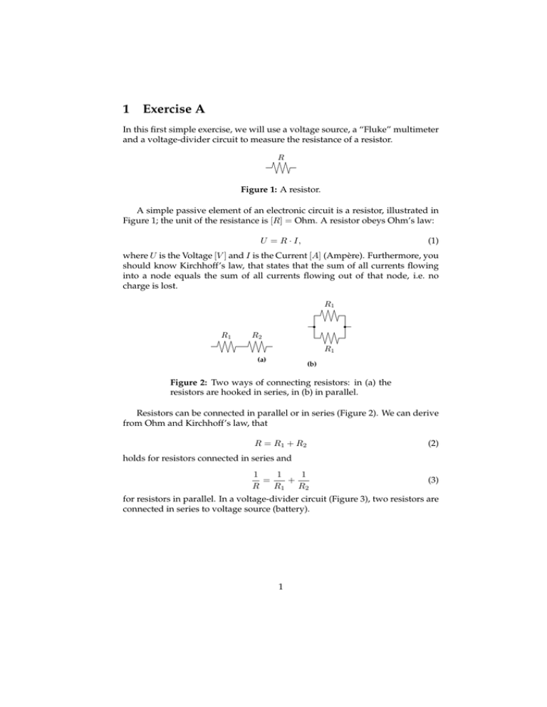
1 Exercise A In this first simple exercise, we will use a voltage source, a “Fluke” multimeter and a voltage-divider circuit to measure the resistance of a resistor. R Figure 1: A resistor. A simple passive element of an electronic circuit is a resistor, illustrated in Figure 1; the unit of the resistance is [R] = Ohm. A resistor obeys Ohm’s law: U = R · I, (1) where U is the Voltage [V ] and I is the Current [A] (Ampère). Furthermore, you should know Kirchhoff’s law, that states that the sum of all currents flowing into a node equals the sum of all currents flowing out of that node, i.e. no charge is lost. R1 R1 R2 R1 (a) (b) Figure 2: Two ways of connecting resistors: in (a) the resistors are hooked in series, in (b) in parallel. Resistors can be connected in parallel or in series (Figure 2). We can derive from Ohm and Kirchhoff’s law, that R = R1 + R2 (2) holds for resistors connected in series and 1 1 1 = + R R1 R2 (3) for resistors in parallel. In a voltage-divider circuit (Figure 3), two resistors are connected in series to voltage source (battery). 1 U R1 R2 Figure 3: A voltage divider. • Assume R1 ≫ R2 ; describe the resistance R of the whole circuit, when R1 and R2 are connected in series and parallel. • The resistance and the precision of a resistor is given by a color code. How does this code work? • By looking at the color codes, find a resistor of 5kΩ resistance (R1 ) and measure it with a Fluke multimeter. Is the measured resistance within the given precision? Do the same for a 1kΩ resistor (R2 ). • Setup a voltage-divider circuit with R1 and R2 connected in series. Use a voltage source to apply a constant voltage U = 1V. Measure the voltage drop U2 accross R2 . • Use Ohm’s law to calculate the resistance R2 as funtion of U , U2 and R1 , R2 = f (U, U2 , R1 ). • Vary U in steps of 100mV from 100mV to 1V, measure U2 and calculate R2 . Are the results constant? Calculate a 95% confidence interval for the mean resistance. Compare this result with the resistance measured with the multimeter. • If y = f (u, v, . . . ), then a small error ∆u, ∆v, . . . will influence the result: ∂f ∆u+ ∂f ∆y = ∂u ∂v ∆v+. . . . Assume there is a error in the voltage measurement of U2 . Write down the formula of error propagation for the function f (U, U2 , R1 ) derived above; use a linear approximation to calculate how a small error of U2 influences the value of the function. 2


