M/s Medha - TrainWeb.org
advertisement
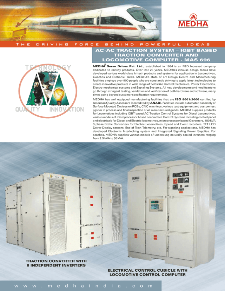
The driving force behind powerful ideas AC-AC TRACTION SYSTEM – IGBT BASED TRACTION CONVERTER AND LOCOMOTIVE COMPUTER - MAS 696 TM MEDHA Servo Drives Pvt. Ltd., established in 1984 is an R&D focussed company dedicated to railway products. Over last 25 years, MEDHA’s inhouse design teams have developed various world class hi-tech products and systems for application in Locomotives, Coaches and Stations/ Yards. MEDHA’s state of art Design Centre and Manufacturing facilities employs over 900 people who are constantly striving to apply latest technologies to create innovative products in wide range of fields like Control Electronics, Power Electronics, Electro-mechanical systems and Signaling Systems. All new developments and modifications go through stringent testing, validation and verification of both hardware and software, many times going beyond customer specification requirements. MEDHA has well equipped manufacturing facilities that are ISO 9001:2000 certified by American Quality Assessors (accredited by ANAB). Facilities include automated assembly of Surface Mounted Devices on PCBs, CNC machines, various test equipment and custom test jigs for in process and final inspection of all manufactured goods. MEDHA supplies products for Locomotives including IGBT based AC Traction Control Systems for Diesel Locomotives, various models of microprocessor based Locomotive Control Systems including control panel and electricals for Diesel and Electric locomotives, microprocessor based Governors, 180 kVA 3 phase Static Converters for Electric Locomotives, Speed and Event recorders, TFT LCD Driver Display screens, End of Train Telemetry, etc. For signaling applications, MEDHA has developed Electronic Interlocking system and Integrated Signaling Power Supplies. For coaches, MEDHA supplies various models of underslung naturally cooled inverters ranging from 2.5 kVA to 50 kVA. TRACTION CONVERTER WITH 6 INDEPENDENT INVERTERS ELECTRICAL CONTROL CUBICLE WITH LOCOMOTIVE CONTROL COMPUTER w w w . m e d h a i n d i a . c o m TRACTION CONVERTER Salient Features B E N E F I T S ! ! ! ! IGBT based design reduces circuit complexity and improves reliability Independent Motor Control enables - Better wheel slip control leading to improved adhesion - Better Tractive Effort independent of wheel diameter variation (variation of wheel diameters allowed within a bogie) - Any failure in Traction Inverter (blower, IGBT, sensor, computer etc) will lead to only one motor being cut-out, hence lesser power reduction compared to bogie cut-out Customizable parameter settings to adapt to different Traction Motor types without changing software In case of Passenger Locomotives, Hotel Load converter (Head End Power) can be installed with some additional space. TRACTION COMPUTERS IGBT PHASE MODULE Independent Traction Inverters ! Six independent Traction Inverters controlling separate Traction Motors ! Each inverter consisting of DC Link Isolation Switch, DC Link capacitor, three phase modules, Traction computer and associated sensors, and one variable speed blower. ! Any failure or fault will lead to only one Traction Inverter / Traction Motor being cut-out. ! Variable blower speeds and cooling irrespective of Companion Alternator output voltage / frequency or Engine speed. IGBT Phase Module (IGBT Stack) ! Each phase module made of two IGBTs of one phase, snubber capacitor, independent Gate Drive cards, independent Gate Drive power supplies, temperature sensors and temperature switches along with heat sink, heat pipes and cooling fins. ! Forced air cooled design with Heat pipe technology. Heat pipes carry heat from heat sink to cooling fins. Forced air passing over cooling fins carries the heat away. ! Gate Drive cards designed to mount directly on IGBTs for proximity and low inductance connections. Communication with Traction computer via Optic Fiber cables. ! Short circuit detection and protection of IGBTs using Vce(sat) desaturation. ! Pulse-by-pulse feedback from Gate drive cards for PWM switching for monitoring by Traction computer. ! Independent Isolated power supplies for each gate drive card. Traction Computers ! Fixed point DSP (Digital Signal Processor) used for implementing core Vector Motor Control. Supervisory Processor for other functions and communications with Locomotive Computer ! Vector Motor Control using Space Vector PWM for complete Variable Voltage Variable Frequency (VVVF) inverter implementation. Motoring and Dynamic Braking operations in full speed range of the motors. ! High switching frequency used in asynchronous PWM mode and six-step mode used at higher speeds. ! Parameter adaptation used with changing operating conditions of the Traction Motor. ! Each Traction Computer controls functions related to one Traction Motor only and are independent from each other. One Power supply card, two Analog signal processing cards, and one computer card (with DSP) make up one set of Traction computer. ! Traction Motor currents, voltages, DC Link voltage, current, temperatures from all IGBTs and capacitors are sensed for monitoring, control and protections. ! All fault diagnostics are available from Locomotive Computer directly. ! Redundant Optic Fiber communication with automatic changeover used for interfacing with Locomotive computer. Protections ! Over current protection for all IGBTs in all Inverters. ! Short circuit protection and open circuit detection in all IGBT gate drive cards ! Over voltage protection using a Brake Chopper to control the voltage to normal range. If this is not sufficient and voltage further shoots up, then a Crowbar circuit is fired to shutdown the complete system. ! Temperature based operating performance deration and eventual shutdown protection for all IGBTs and capacitors. In case of sensor failure, temperature switches provided for additional layer of protection. ! Traction Motor temperature based torque deration and eventual shutdown for protecting motor against high temperatures. ! Traction speed sensor health monitoring and Inverter shutdown in case of failures. ! Health Monitoring of individual Gate Drive Power supplies and protections in case of failures. ! Blower motor / inverter currents and speed monitoring for protections. LOCOMOTIVE CONTROL COMPUTER Salient Features Alternator Excitation and Propulsion Control ! Continuously monitors driver requests and controls DC Link Voltage to desired values dependent on Engine RPM and Locomotive speed. SCR bridge circuit between Companion Alternator armature and Traction Alternator field winding is used to control excitation. ! Alternator excitation is controlled to maintain constant Gross Horse Power (GHP) load on the Diesel engine. ! Individual Traction Inverters are commanded to maintain the desired torque. Individual inverters can be cut-out using separate DC Link Isolation Switches. Wheel Slip Control ! Improved adhesion using Wheel Creep philosophy. ! Individual speeds of all 6 axles are measured and individual Inverter Torque commands controlled to deliver maximum possible Tractive Effort. Fault Diagnostics and Tolerance ! Comprehensive Fault Diagnostics with fault tolerance to allow limited operations in spite of the faults. All fault logs are accompanied by comprehensive fault data packs to aid the maintenance staff in analyzing and identifying the root-cause of problems. ! Automatic Fault Recovery recognition and intimation to driver ! Fault viewing and clearing via display or laptop, with 3 different password protected access levels depending on criticality of faults. Inputs, Outputs, Sensors ! Non-contact Hall effect sensors for current and voltage measurements ! All input and output interfaces to locomotive signals of 74VDC are optically isolated, reverse polarity and surge protected. Outputs are further overload and short circuit protected. Locomotive Equipment Protection ! Monitors currents, voltages and temperatures of Engine, Alternator, Traction Motors, etc and controls them to operate within set limits. ! Engine protections like Low water, Low Lube Oil Pressure, High temperature, mechanical speed limit etc. Programmable Parameters and Display ! Various user programmable parameters can be set via a Laptop. System has been customized to various types of locomotives with different types of Traction equipment without software changes. ! 256x64 Graphical VFD display with fixed and context sensitive keypad ! Menu driven user selectable continuous display of various groups of operating parameters on the Display Unit. Event Recorder ! Built in Event Recorder for recording operational parameters of locomotive in both internal and external memories. ! Statistics like lifetime counters, trip counters and notch-wise counters for energy generated, distance traveled and engine run time. Other Features ! Vigilance Control (Driver Alerter) to ensure driver alertness ! USB port for downloading and programming all data. ! Manual and auto test modes to help maintenance staff identify problems. ! Self load test using dynamic brake resistors as electrical load. ! Automatic Emergency Brake to avoid runaway train on steep gradients. Add-on Modules / Features: ! Automatic Engine Start Stop or Auxiliary Power Unit functionality for Fuel savings. ! Remote Monitoring of Locomotives for health status, faults, etc. using wireless communications and Internet Server. ! Distributed Power Control Enabled for future addition. ! Computer Controlled Brake System interface. ! LCD TFT Driver Display interface. B E N E F I T S ! ! ! ! ! ! Improves Locomotive Availability (reduced down times) Improves Adhesion with Independent Motor Control philosophy Improves Engine Utilization (GHP based control) Monitors all Traction Equipment on-board for Safe Operating Margins Customizable parameter settings to adapt to different locomotive types without changing software Modular expandable platform for added functionality like Automatic Engine Start Stop, Remote Monitoring, Distributed Power Control etc for fuel savings, increased availability and monitoring. DISPLAY UNIT LOCOMOTIVE CONTROL COMPUTER Technical Specifications for Traction Converter DC Link Voltage : Variable from 600V to 2600V DC (max operating up to 3000V followed by protections up to 3400V) Rated Output Voltage : 3phase, 2150V rms (higher voltages possible) Required Output Power : 520kW per inverter or 3.1MW for all 6 motors (higher powers are possible) Control Voltage : 50 to 100 V DC Traction Control : PWM Control : = Independent Motor Control = Vector Motor control with parameter adaptation Space Vector PWM with asynchronous and six step modes Braking : Full range of Dynamic Braking Control Communication : CAN interface with Locomotive Computer using Optic Fiber Cables Processors : 16-bit High speed DSP, with additional supervisory processor for certain ancillary functions, communication and protections. Technical Specifications for Locomotive Computer Power Supply Digital Inputs : : RPM Inputs : Analog Inputs : Digital Outputs : PWM Output : Analog Output Fault Log Memory : : Communication Ports : Display / Keyboard : Indications : Interconnections : Protections : TM MEDHA 74 V DC nominal 144 inputs for interfacing 74VDC signals. Optically isolated, reverse polarity and surge protected 6 inputs for signals like Radar, Turbo and Engine speed Precalibrated 40 inputs for interfacing Voltage, Current, Temperature and Pressure Signals 80 outputs Optically isolated, reverse polarity, surge, overload and short circuit protected outputs for driving 74VDC loads For Auxiliary Generator(Battery charging) output control 2 outputs for driving Tractive Effort and Speed dials More than 500 faults with Date/Time stamps and more than 900 fault Data packs in Non Volatile Flash Memory • RS 485 Port for Display Unit • RS 485 for Distributed Power Control System • RS 485 for Electronic Air Brake System • USB Port for Configuration setting and Faults Log, Data pack and Event Recorder Data download • RS 485 for LCD TFT Driver display interface • Dual redundant Optical Fiber Link for communication with Traction Computers 256 x 64 Graphical Vacuum Fluorescent Display 29 key Membrane keyboard LED indications on individual cards for health indication Polarized MS Round Circular Threaded Connectors or Bayonet Connectors EMI, EMC, and ESD protections MEDHA SERVO DRIVES PVT. LTD. P-4/5B, I.D.A., Nacharam, Hyderabad- 500 076. INDIA, Ph: +91-40-27173990, Fax: +91-40-27174908, e-mail: marketing@medhaindia.com, exports@medhaindia.com
