Integrated Illumination Systems, Inc.
355 Bantam Lake Road
Morris, CT 06763 USA
i2Cove
tel +1.860.567.0708
fax +1.860.567.2501
Asymmetrical Installation Instructions
support@i2Systems.com
www.i2Systems.com
Before you begin, read these instructions completely and carefully. If you have any
questions regarding the proper use, installation, or safety considerations of this product,
please visit our website or contact i2Systems Customer Support @ 860.567.0708.
DANGER: RISK OF ELECTRICAL SHOCK OR FIRE.
DISCONNECT POWER BEFORE INSTALLATION.
Electrical Specifications
PARAMETER
VALUE
Input Power
8 Watts* / Ft
Input Voltage
120-277V AC, 50/60 Hz
Max. Fixture Run Length
8 Watts: 120VAC: 60 Ft
208VAC: 100 Ft
240VAC: 100 Ft
277VAC: 100 Ft
LED Color (CCT)
2700 K, 3000 K, 3500 K
LED Color Consistency
2-Step MacAdam Ellipse
Temperature
Operating: -20°C to +40°C
Startup: -20°C to +40°C
Storage: -30°C to +60°C
Relative 10 - 90%
Humidity: (non-condensing)
Driver
Integrated
Dimming
Between 10% and 100% via
0 - 10 VDC
WARNING: Risk of fire or electric shock. Installation of LED fixture requires knowledge
of electrical systems. If not qualified, do not attempt installation. Contact qualified
electrician.
This luminaire must be installed in accordance to your local electrical code. If you are not
familiar with these codes and requirements, consult a qualified electrician.
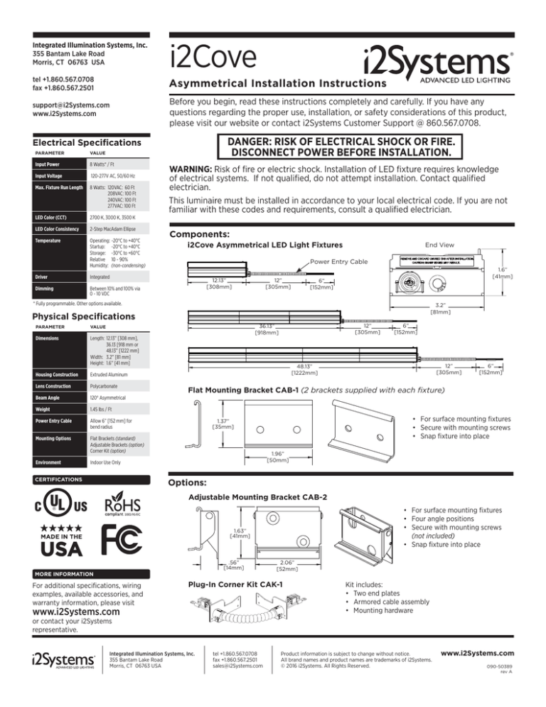
Components:
i2Cove Asymmetrical LED Light Fixtures
End View
Power Entry Cable
12”
[305mm]
12.13”
[308mm]
1.6”
[41mm]
6”
[152mm]
* Fully programmable. Other options available.
3.2”
[81mm]
Physical Specifications
12”
[305mm]
36.13”
[918mm]
PARAMETER
VALUE
Dimensions
Length: 12.13” [308 mm],
36.13 [918 mm or
48.13” [1222 mm]
Width: 3.2” [81 mm]
Height: 1.6” [41 mm]
Housing Construction
Extruded Aluminum
Lens Construction
Polycarbonate
Beam Angle
120° Asymmetrical
Weight
1.45 lbs / Ft
Power Entry Cable
Allow 6” [152 mm] for
bend radius
Mounting Options
Flat Brackets (standard)
Adjustable Brackets (option)
Corner Kit (option)
Environment
Indoor Use Only
CERTIFICATIONS
6”
[152mm]
12”
[305mm]
48.13”
[1222mm]
6”
[152mm]
Flat Mounting Bracket CAB-1 (2 brackets supplied with each fixture)
• For surface mounting fixtures
• Secure with mounting screws
• Snap fixture into place
1.37”
[35mm]
1.96”
[50mm]
Options:
Adjustable Mounting Bracket CAB-2
• For surface mounting fixtures
• Four angle positions
• Secure with mounting screws
(not included)
• Snap fixture into place
1.63”
[41mm]
.56”
[14mm]
2.06”
[52mm]
MORE INFORMATION
For additional specifications, wiring
examples, available accessories, and
warranty information, please visit
Plug-In Corner Kit CAK-1
www.i2Systems.com
Kit includes:
• Two end plates
• Armored cable assembly
• Mounting hardware
or contact your i2Systems
representative.
Integrated Illumination Systems, Inc.
355 Bantam Lake Road
Morris, CT 06763 USA
tel +1.860.567.0708
fax +1.860.567.2501
sales@i2Systems.com
Product information is subject to change without notice.
All brand names and product names are trademarks of i2Systems.
© 2016 i2Systems. All Rights Reserved.
www.i2Systems.com
090-50389
rev A
i2Cove Asymmetrical Installation Instructions
INSTALLATION INSTRUCTIONS
DANGER: RISK OF ELECTRICAL SHOCK OR FIRE. DISCONNECT POWER BEFORE INSTALLATION.
Adhere to local electrical codes. If you are not familiar with these codes, consult a qualified electrician.
1
Verify the input current and fixture wattage. There is a label on each fixture which outlines the acceptable input voltage as well as
the watts per foot at 50/60 Hz. The input Voltage AC and the wattage of the fixture will determine the fixture run length.
Watts / Foot
Exceeding the voltage input and acceptable fixture run lengths will result in damage to the lighting fixture and pose a serious
safety hazard.
Input
5W Max. Run
8W Max. Run
10W Max. Run
12W Max. Run
120 VAC
208VAC
240VAC
277 VAC
100 ft
100 ft
100 ft
100 ft
60 ft
100 ft
100 ft
100 ft
50 ft
80 ft
100 ft
100 ft
40 ft
70 ft
80 ft
90 ft
Review the length of fixture(s) and cable(s).
Power entry unit comes with a 12” cable.
Power Entry Cable
Length
12”
[305mm]
6”
[152mm]
Additional units are supplied with a 6” jumper cable.
Use supplied jumper cable
685-50140 to connect units
together.
Fixtures can be installed in a variety of configurations: linearly, around corners, or around curved spaces.
Use Corner Kit CAK-1 for
non-linear installations.
Refer to Section A on page 4.
Corner Kit cable is 6” long.
Integrated Illumination Systems, Inc.
355 Bantam Lake Road
Morris, CT 06763 USA
tel +1.860.567.0708
fax +1.860.567.2501
sales@i2Systems.com
Product information is subject to change without notice.
All brand names and product names are trademarks of i2Systems.
© 2016 i2Systems. All Rights Reserved.
www.i2Systems.com
090-50389
rev A
i2Cove Asymmetrical Installation Instructions
INSTALLATION INSTRUCTIONS (CONT’D)
DANGER: RISK OF ELECTRICAL SHOCK OR FIRE. DISCONNECT POWER BEFORE INSTALLATION.
Adhere to local electrical codes. If you are not familiar with these codes, consult a qualified electrician.
2
Install mounting brackets to the building along the desired path of fixtures.
Both fixed and adjustable mounting brackets are available.
Fixed Bracket CAB-1.
Two brackets are supplied with each fixture.
Adjustable Bracket CAB-2 (optional).
Secure using two screws (not included).
Correctly position the angle of
each bracket after snapping in
the light.
Use two screws per bracket
(screws not included).
Two brackets per fixture are recommended.
3
Install lights in a series, snapping lights into brackets and attaching ground clips between fixtures.
Affix the brackets and snap down lights
with the jumper cable attached.
(Fixed bracket shown)
Attach a ground clip provided such that
it bridges two lights in series together.
Gently tap the clip into place and then
attach with a screw (not included).
4
Attach the dimming wires to the 0 - 10 VDC dimming supply. Do not use a higher voltage as this will result in damage to the fixture.
If the dimming option is not used, attach wire nuts to cap off wires. The i2Cove has the ability to dim 10% to 100%.
Cut supplied 18” armored cable down (if needed) to reach building power junction box and protect wires on end with protective
bushing.
LINE
WHITE
NEUTRAL
GREEN
GROUND
GRAY
VDC (-)
VIOLET
VDC (+)
3rd Party
Junction Box
Junction box
(supplied by others)
Integrated Illumination Systems, Inc.
355 Bantam Lake Road
Morris, CT 06763 USA
BLACK
tel +1.860.567.0708
fax +1.860.567.2501
sales@i2Systems.com
Product information is subject to change without notice.
All brand names and product names are trademarks of i2Systems.
© 2016 i2Systems. All Rights Reserved.
120 - 277 VAC
3rd PARTY
0 - 10 VDC
DIMMER
Dimming
Optional
www.i2Systems.com
090-50389
rev A
i2Cove Asymmetrical Installation Instructions
OPTIONAL COMPONENTS
DANGER: RISK OF ELECTRICAL SHOCK OR FIRE. DISCONNECT POWER BEFORE INSTALLATION.
Adhere to local electrical codes. If you are not familiar with these codes, consult a qualified electrician.
A
Install the Corner Kit if you wish to go around a corner. Match the right and left plates with the light.
Plug 6-position female connector into mating
connector on light. (2 places)
Maximum bend
this position
Using screws provided, mount plates to lights.
(3 screws per plate)
B
Move Power Entry to other end of the light (optional).
The power entry box and cable are supplied on the right side of the unit, but can be moved to the left.
If you choose to keep it on the right side (as shipped), attach the Left End Plate and insert Hole Plug provided:
Insert Hole Plug into End Plate.
Follow the instructions on the label: remove unused tab
Using 3 screws, attach Left End Plate.
REMOVE AND DISCARD UNUSED TAB AFTER INSTALLATION.
CAUTION: SHARP EDGES MAY RESULT.
If you choose to move Power Entry to the left side, first, remove it from right side:
Remove 2 mounting screws, unplug connector, and
remove Power Entry Cable Assembly from right side.
LEFT SIDE
RIGHT SIDE
Then, install Power Entry on left side:
Using 3 screws, attach Right End Plate provided.
Plug Power Entry Cable into the mating connector on
the right side and reattach Assembly using 2 screws.
Insert Hole Plug
into End Plate.
Follow the instructions on the label: remove unused tab
RIGHT SIDE
REMOVE AND DISCARD UNUSED TAB AFTER INSTALLATION.
CAUTION: SHARP EDGES MAY RESULT.
LEFT SIDE
Integrated Illumination Systems, Inc.
355 Bantam Lake Road
Morris, CT 06763 USA
tel +1.860.567.0708
fax +1.860.567.2501
sales@i2Systems.com
Product information is subject to change without notice.
All brand names and product names are trademarks of i2Systems.
© 2016 i2Systems. All Rights Reserved.
www.i2Systems.com
090-50389
rev A
i2Cove Asymmetrical Installation Instructions
DANGER: RISK OF ELECTRICAL SHOCK OR FIRE. DISCONNECT POWER BEFORE INSTALLATION.
Read and understand the installation instructions before attempting to install or use the fixture. It is the responsibility of the
contractor, installer, purchaser, owner and user to install, maintain, and operate i2Cove fixtures in such a manner as to comply
with all applicable codes, state and local laws, ordinances, and regulations. Consult with the appropriate electrical inspector to
ensure compliance.
INSTALLATION / THERMALS
ELECTRICAL WARNINGS AND CAUTIONS
• DANGER: RISK OF ELECTRICAL SHOCK OR FIRE.
DISCONNECT POWER BEFORE INSTALLATION.
• WARNING: Do not use a fixture for any voltage for which it
is not rated. Do not exceed the specified voltage and current
input for any fixture. Each unit contains a label outlining the
fixture wattage. The label also contains the part number,
date manufactured, and individual serial number assigned to
the fixture.
Model/Part Number
Serial Number
• WARNING: Ensure that main power supply is off before
installing or wiring a fixture.
• WARNING: Risk of fire or electric shock, installation requires
knowledge of luminaire electrical systems. Luminaires must
be installed by a qualified electrician according to local and
national codes for proper installation.
• WARNING: Risk of fire or electric shock. Luminaire wiring
and electrical parts may be damaged when drilling.
• WARNING: To prevent wiring damage or abrasion, do not
expose wiring to edges of sheet metal or other sharp objects.
• Only use fixtures with voltage for which it is rated. Do not
exceed the specified input voltage and current.
• Fixtures have line voltage risk of shock and no user
serviceable parts. Do not attempt to open.
• Do not use a fixture if the lens, housing, or power cables are
damaged.
• Do not hot swap fixtures. Ensure that power to the series is
off before connecting or disconnecting individual fixtures.
• Contractor is responsible for adequately reinforcing walls
and/or ceilings to support luminaire weight. i2Systems
accepts no responsibility for inadequately reinforced walls
and/or ceilings.
• Do not make or alter any open holes in an enclosure of
wiring or electrical components during installation.
• Wear proper safety equipment and follow appropriate safety
precautions.
• Connect to a properly grounded branch circuit protected by
a circuit breaker or fuse.
• Always use i2Systems and/or i2Systems-recommended
electrical components.
• For use on systems with voltages greater than the maximum
rated voltage, use a safety agency approved, step-down
power supply to convert the higher voltage to a voltage
within the specified operating range of the fixture.
• Once installed, monitor the fixture case temperature. The
fixture case temperature should not exceed 50°C at worst
case ambient. Should the case temperature exceed the
max rating of 50°C, do one or more of the following: reduce
the ambient temperature, heatsink the fixture, increase the
airflow or volume of air around the fixture, or remove the
fixture and install a lower power fixture.
• Do not install the light fixture where any liquid will come in
contact with the luminaire or the wiring. Do not install the
light fixture where it will sit in any liquid or where liquid will
collect, pool or puddle. Fixture is suitable for indoor dry
locations only.
• It is recommended that the light fixture remain in its original
container until it is ready to be installed.
FCC NOTICE
The hardware device complies with Part 15 of the FCC Rules.
Operation is subject to the following two conditions:
1. This device may not cause harmful interference, and
2. This device must accept any interference received,
including interference that may cause undesired
operation.
This equipment has been tested and found to comply with
the limits for a Class A device, pursuant to Part 15 of the FCC
regulations. These limits are designed to provide reasonable
protection against harmful interference in a residential or
commercial installation. However there is no guarantee that
interference will not occur in a particular installation. This
equipment generates, uses, and can radiate radio frequency
energy and, if not installed or used in accordance with
the instructions, may cause harmful interference to radio
communications. If this equipment does cause harmful
interference to radio of television reception, which can be
determined by turning the equipment off and on, the user is
encouraged to try to correct the interference by one or more
of the following measures:
1. Reorient or relocate the receiving antennae;
2. Increase the separation between the equipment and the
receiver;
3. Connect the equipment to an outlet on a circuit different
from that to which the receiver is connected;
4. Consult the dealer or an experienced radio/TV
technician for help.
Any changes or modifications not expressly approved by
the party responsible for compliance could void the user’s
authority to operate the equipment. Where shielded
interface cables have been provided with the product or
specified accessories elsewhere defined to be used with the
installation of the product, they must be used in order to
ensure compliance with FCC regulations.
WARRANTY AND MAINTENANCE
The linear lighting that you have purchased is a self-contained system; do not attempt to repair or disassemble the light.
There is no recommended maintenance for this product.
For a copy of our limited warranty please visit www.i2Systems.com.
Integrated Illumination Systems, Inc.
355 Bantam Lake Road
Morris, CT 06763 USA
tel +1.860.567.0708
fax +1.860.567.2501
sales@i2Systems.com
Product information is subject to change without notice.
All brand names and product names are trademarks of i2Systems.
© 2016 i2Systems. All Rights Reserved.
www.i2Systems.com
090-50389
rev A

