IT Essentials: PC Hardware and Software v4.1
Chapter 11 – Lab/Student
11.2.2 Lab: Using a Multimeter and a Power Supply Tester
Introduction
Print and complete this lab.
In this lab, you will learn how to use and handle a multimeter and a power supply tester.
Recommended Equipment
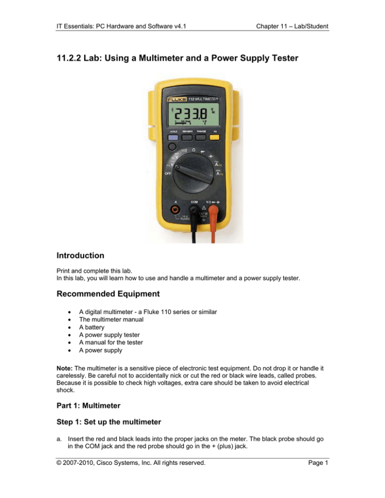
A digital multimeter - a Fluke 110 series or similar
The multimeter manual
A battery
A power supply tester
A manual for the tester
A power supply
Note: The multimeter is a sensitive piece of electronic test equipment. Do not drop it or handle it
carelessly. Be careful not to accidentally nick or cut the red or black wire leads, called probes.
Because it is possible to check high voltages, extra care should be taken to avoid electrical
shock.
Part 1: Multimeter
Step 1: Set up the multimeter
a. Insert the red and black leads into the proper jacks on the meter. The black probe should go
in the COM jack and the red probe should go in the + (plus) jack.
© 2007-2010, Cisco Systems, Inc. All rights reserved.
Page 1
IT Essentials: PC Hardware and Software v4.1
Chapter 11 – Lab/Student
b. Turn on the multimeter.(Consult the manual if there is no ON/OFF switch.)
What is the model of the multimeter?
What action must be taken to turn the meter on?
Step 2: Explore the different multimeter measurements
a. Switch or turn to different measurements. For example, switch the multimeter to ohms.
How many different switch positions does the multimeter have?
What are they?
b. Switch or turn the multimeter to the voltage measurement.
What is the symbol shown for this?
Step 3: Measure the voltage of a battery
Place the battery on the table. Touch the tip of the red (positive) probe on the positive side of a
battery. Touch the tip of the black, (negative) probe on the other end of the battery.
What is shown on the display?
If the multimeter does not display a number close to the battery voltage, check the multimeter
setting to ensure it is set to measure voltage, or replace the battery with a known good battery. If
the number is a negative number, reverse the probes.
Name one thing that you should not do when using multimeter.
Name one important function of a multimeter.
Disconnect the multimeter from the battery. Switch the multimeter to OFF. Part 1 of the lab is
complete. Have your instructor verify your work.
© 2007-2010, Cisco Systems, Inc. All rights reserved.
Page 2
IT Essentials: PC Hardware and Software v4.1
Chapter 11 – Lab/Student
Part 2: Power Supply Tester
Complete only the steps for the connectors supported by the power supply tester that you are
using.
Step 1: Check the testing ports for the Power Supply Tester
Many power supply testers have connector ports to test the following power supply connectors:
20-pin/24-pin motherboard connector
4-pin Molex connector
6-pin PCI-E connector
P4 +12V connector
P8 +12V EPS connector
4-pin Berg connector
5-pin SATA connector
Which connectors does the power supply tester you are using have?
Complete the following steps for the connectors supported by the power supply tester that you
are using.
Step 2: Test the Power Supply Motherboard Connector
a. Set the power supply switch (if available) to the OFF (or 0) position.
b. Plug the 20-pin or 24-pin motherboard connector into the tester.
c.
Plug the power supply into an AC outlet.
d. Set the power supply switch (if available) to the ON (or 1) position.
If the power supply is working, LEDs will illuminate and you might hear a beep. If the LED lights
do not illuminate, it is possible the power supply might be damaged or the motherboard connector
has failed. In this instance, you must check all connections, ensure the power supply switch (if
available) is set to ON (or 1) and try again. If the LEDs still do not illuminate, consult your
instructor.
Possible LED lights include +5 V, -5 V, +12 V, +5 VSB, PG, -12 V, +3.3 V.
Which LED lights are illuminated?
Step 3: Test the Power Supply Molex Connector
Plug the 4-pin Molex connector into the tester. The LED illuminates on +12 V and +5 V. (If the
power output fails, the LEDs will not illuminate.)
Which LED lights are illuminated?
Step 4: Test the 6-pin PCI-E connector
Plug the 6-pin PCI-E connector into the tester. The LED will illuminate on +12 V. (If the power
© 2007-2010, Cisco Systems, Inc. All rights reserved.
Page 3
IT Essentials: PC Hardware and Software v4.1
Chapter 11 – Lab/Student
output fails, the LED will not illuminate.)
Does the LED light illuminate?
Step 5: Test the 5-pin SATA connector
Plug the 5-pin SATA connector into the tester. The LED will illuminate on +12 V, +5 V, and +3.3
V. (If the power output fails, the LEDs will not illuminate.)
Which LED lights are illuminated?
Step 6: Test the 4-pin Berg connector
Plug the 4-pin Berg connector into the tester. The LED will illuminate on +12 V and +5 V. (If the
power output fails, the LEDs will not illuminate.)
Which LED lights are illuminated?
Step 7: Test the P4/P8 connectors
a. Plug the P4 +12 V connector into the tester. The LED will illuminate on +12 V. (If the power
output fails, the LEDs will not illuminate.)
b. Plug the P8 +12 V connector into the tester. The LED will illuminate on +12 V. (If the power
output fails, the LEDs will not illuminate.)
c.
Which LED lights are illuminated?
Switch the power supply to OFF (or 0) if available. Disconnect the power supply from the AC
outlet. Disconnect the power supply from the power supply tester. The lab is complete. Have your
instructor verify your work.
© 2007-2010, Cisco Systems, Inc. All rights reserved.
Page 4


