PowerPact™ H-, J-, and L-Frame Circuit Breakers
Circuit Breaker Mounting and Connections
Connection
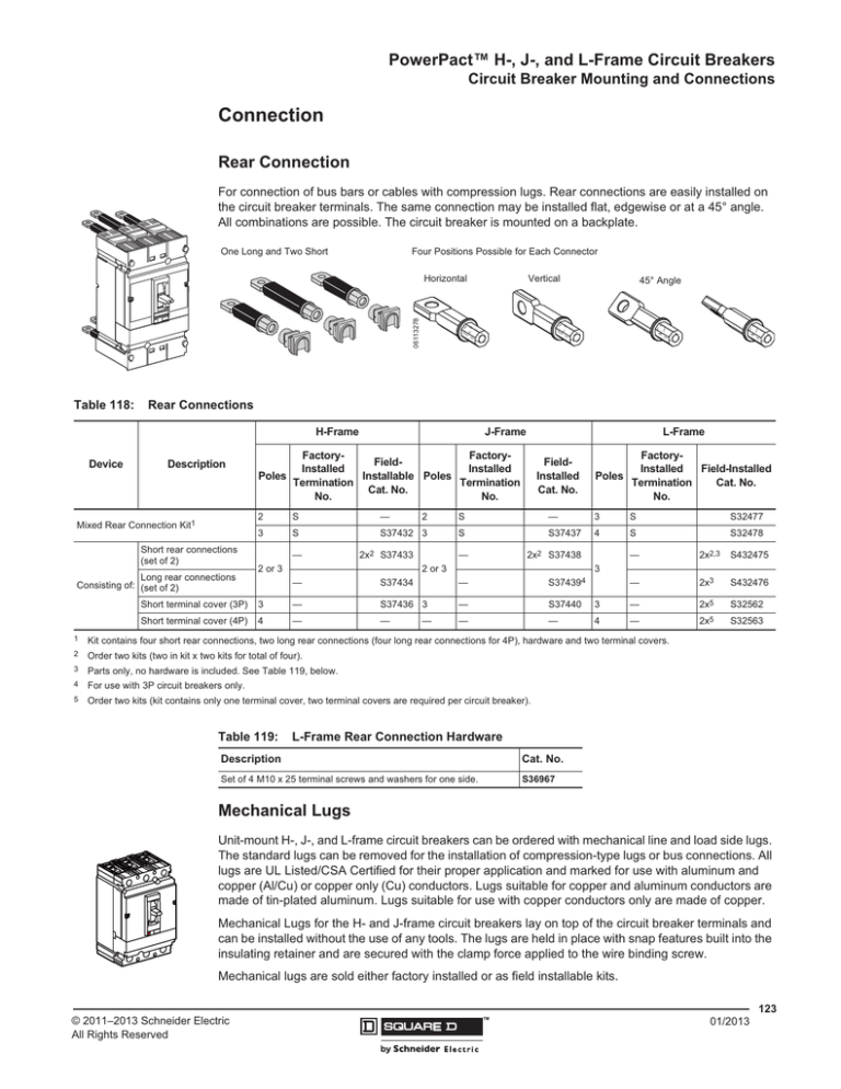
Rear Connection
For connection of bus bars or cables with compression lugs. Rear connections are easily installed on
the circuit breaker terminals. The same connection may be installed flat, edgewise or at a 45° angle.
All combinations are possible. The circuit breaker is mounted on a backplate.
One Long and Two Short
Four Positions Possible for Each Connector
push
to
trip
Table 118:
45° Angle
Rear Connections
H-Frame
Device
Vertical
06113278
Horizontal
Description
Mixed Rear Connection Kit1
Short rear connections
(set of 2)
Long rear connections
Consisting of: (set of 2)
J-Frame
L-Frame
FactoryFactoryFieldInstalled
Installed
Installable Poles
Poles
Termination
Termination
Cat. No.
No.
No.
FieldInstalled
Cat. No.
FactoryField-Installed
Installed
Poles
Cat. No.
Termination
No.
2
S
—
2
S
—
3
S
S32477
3
S
S37432 3
S
S37437
4
S
S32478
—
2x2 S37433
2 or 3
2x2 S37438
—
2 or 3
—
S37434
—
2x2,3
S432475
—
2x3
S432476
3
S374394
—
Short terminal cover (3P)
3
—
S37436 3
—
S37440
3
—
2x5
S32562
Short terminal cover (4P)
4
—
—
—
—
4
—
2x5
S32563
—
1
Kit contains four short rear connections, two long rear connections (four long rear connections for 4P), hardware and two terminal covers.
2
Order two kits (two in kit x two kits for total of four).
3
Parts only, no hardware is included. See Table 119, below.
4
For use with 3P circuit breakers only.
5
Order two kits (kit contains only one terminal cover, two terminal covers are required per circuit breaker).
Table 119:
L-Frame Rear Connection Hardware
Description
Cat. No.
Set of 4 M10 x 25 terminal screws and washers for one side.
S36967
Mechanical Lugs
Unit-mount H-, J-, and L-frame circuit breakers can be ordered with mechanical line and load side lugs.
The standard lugs can be removed for the installation of compression-type lugs or bus connections. All
lugs are UL Listed/CSA Certified for their proper application and marked for use with aluminum and
copper (Al/Cu) or copper only (Cu) conductors. Lugs suitable for copper and aluminum conductors are
made of tin-plated aluminum. Lugs suitable for use with copper conductors only are made of copper.
Mechanical Lugs for the H- and J-frame circuit breakers lay on top of the circuit breaker terminals and
can be installed without the use of any tools. The lugs are held in place with snap features built into the
insulating retainer and are secured with the clamp force applied to the wire binding screw.
Mechanical lugs are sold either factory installed or as field installable kits.
123
© 2011–2013 Schneider Electric
All Rights Reserved
™
01/2013
PowerPact™ H-, J-, and L-Frame Circuit Breakers
Circuit Breaker Mounting and Connections
Table 120:
Mechanical Lug Kits for H-Frame and J-Frame Circuit Breakers
Circuit Breaker Application
Ampere
Rating
Standard
Al Lugs for Use
with Al or Cu Wire
Optional
Number of Wires
Per Lug and Wire
Range
Ampere
Rating
HD, HG, HJ, HL
15–150 A
(1) 14–3/0 AWG Al or Cu AL150HD
3
JD, JG, JJ, JL
150–175 A
(1) 4-4/0 AWG Al or Cu
AL175JD
3
JD, JG, JJ, JL
200–250 A
(1) 3/0–350 kcmil Al or Cu AL250JD
3
Cu Lugs for Use
with Cu Wire Only
JD,JG,JJ,JL
150–175 A
HD,HG,HJ,HL 15–150 A
(1) 14–2/0 AWG Cu
JD,JG,JJ,JL
(1) 1/0–300 kcmil Cu
150–250 A
CU250JD
3
S37423
2
Control Wire Terminal for J-frame lug kit
S37424
2
Mechanical Lug Kits for L-Frame Circuit Breakers1
Circuit Breaker Application
Unit
Ampere
Poles
Mount
Rating
250
Al Lugs for Use
with Al or Cu Wire 400/600
Qty Type of
Per Termina
Kit l Shield3
3
X
X
(1) 2 AWG–500 kcmil Al
AL400L61K3
3
Short
4
X
—
(1) 2 AWG–600 kcmil Cu
AL400L61K4
4
Short
3
Medium
4
Medium
X
(2) 3/0 AWG–500 kcmil Al or Cu AL600LF52K3
3
Short
X
X
(1) 2 AWG–500 kcmil Al
CU400L61K3
3
Short
4
X
—
(1) 2 AWG–600 kcmil Cu
CU400L61K4
4
Short
Cu Lugs for Use
with Cu Wire Only 400/600
3
X
—
CU600LS52K3
3
Medium
4
X
—
CU600LS52K4
4
Medium
400/600
3
X
X
(1) 3/0 AWG–500 kcmil Al or Cu CU600LF52K3
3
Short
06163037
06163038
Kit Cat. No.
AL600LS52K3
250/400
600 A Lug
AL600LF52K3
I-Line
Number of Wires
Per Lug and Wire Range2
AL600LS52K4
400/600
600 A Lug
AL600LS52K3
CU150HD 3
Control Wire Terminal for H-frame lug kit
Table 121:
400 A Lug
AL400L6IK3
Qty
Per
Kit
Kit Cat.
No.
3
X
—
4
X
—
3
X
3
(2) 2/0 AWG–500 kcmil Al or Cu
(1) 2/0 AWG–500 kcmil Al or Cu
1
For lug pack information, see Figure 31 on page 161.
2
For control wire installation, use an 8-32 x 1/4 in. screw (not provided) into tapped control wire hole in lower left hand corner of lug.
3
For terminal shield dimensions, see Figure 31 on page 161.
Voltage Takeoff (Control Wire Terminals) for Mechanical Lugs and
Terminal Nuts
06113294
Mechanical Lug Control
Wire Terminal
Control
Wire
Hole
Powerpact H- and J-Frame mechanical lugs may be equipped with a separate control wire termination.
The kit is available factory installed or as a field installable kit. The adaptor is secured underneath the
lug and has a tab extension suitable for attachment of a 0.250 inch slip-on connector.
All L-frame mechanical lugs are pre-tapped for control wires. For control wire installation, use an 8-32
x 1/4 in. screw (not provided) into tapped control wire hole in lower left hand corner of the lug.
Fully insulated type connectors must be used to prevent live parts from extending into the wiring gutter
area.
Table 122:
Busbar Control Wire
Terminal
Control Wire Terminals
Description
Frame
Cat. No.
Qty Per Kit
06114127
Mechanical Lugs
Control Wire Terminal for H-Frame Lugs
HD/HG/HJ/HL
S37423
2
Control Wire Terminal for J-Frame Lugs
JD/JG/JJ/JL
S37424
2
2
Busbar Connection
Control Wire Terminal for H-Frame Terminal Nut
HD/HG/HJ/HL
S37429
Control Wire Terminal for J-Frame Terminal Nut
JD/JG/JJ/JL
S37430
2
Control Tap takeoff
L-Frame
29348
2
124
01/2013
™
© 2011–2013 Schneider Electric
All Rights Reserved
PowerPact™ H-, J-, and L-Frame Circuit Breakers
Circuit Breaker Mounting and Connections
Bus-Bar Connections
The H-, J- and L-frame circuit breakers may be equipped with captive nuts and screws for direct
connection to bars or to compression (crimp) lugs
For L-frame, the mechanical lug can be removed, leaving the threaded nut insert intact. This
configuration may be ordered with the suffixes described below. Connection hardware (terminal
screws) must be ordered as in table 123.
Table 123:
Factory-Installed Terminal Nut Inserts for Bus or Crimp Lug Connection
Cat. No. Termination
(Position 4)
Special Terminations
Options
Description
F
Terminal nut insert on both ends; no lugs either end
M
Terminal nut insert on OFF end; lugs on ON end only
P
Terminal nut insert on ON end; lugs on OFF end only
A
-TA
I-Line on ON end; English terminal nuts on OFF end1
A
-TB
I-Line on ON end; Metric terminal nuts on OFF end1
F, M, or P
-TW
For -F-, Metric terminal nuts on both ends1
F, M, or P
-TX
1
For -P, Metric terminal nuts on ON end; lugs on OFF end
For H- and J-frame only. L-frame terminal nuts are metric only.
Table 124:
Terminal Nut Insert
For -M, lugs on ON end; Metric terminal nuts on OFF end
Terminal Nuts for Bus Bar Connection of H-Frame and J-Frame Circuit Breakers
Description1
Frame
Tap
Cat. No.
Qty Per Kit
H-Frame Terminal Nut Insert–English
HD/HG/HJ/HL
1/4-20
S37425
2
H-Frame Terminal Nut Insert–English
HD/HG/HJ/HL
1/4-20
S37444
3
H-Frame Terminal Nut Insert–Metric
HD/HG/HJ/HL
M6
S37426
2
J-Frame Terminal Nut Insert–English
JD/JG/JJ/JL
1/4-20
S37427
2
J-Frame Terminal Nut Insert–English
JD/JG/JJ/JL
1/4-20
S37445
3
J-Frame Terminal Nut Insert–Metric
JD/JG/JJ/JL
M8
S37428
2
1
Torque
80–90 lb-in
(9–10.2 N•m)
80–90 lb-in
(9–10.2 N•m)
Screws not included.
Table 125:
Bar Dimensions
Dimension
H-Frame
J-Frame
L-Frame
A
0.250 in.
(6.4 mm)
0.3125 in.
(7.9 mm)
0.4 in.
(10 mm)
B
0.125–0.375 in.
(3.2–9.5 mm)
0.125–0.375 in.
(3.2–.5 mm)
0.11–0.39 in.
(3–10 mm)
C
0.50 in.
(12.7 mm)
0.50–0.75 in.
(12.7–1.1 mm)
1.35 in.
(32 mm)
D
0.3 in.
(7.6 mm)
0.625 in.
(15.9 mm)
<0.51 in.
13 mm)
E
0.3 in.
(7.6 mm)
0.375 in.
(9.5 mm)
0.64 in.
(16 mm)
Table 126:
B
06113283
06113279
For H- and J-frame, these are readily field-installable, simply by removing the mechanical lug and
replacing with the appropriate terminal nut inset described in Table 123. They are also available
factory-installed, using the Product Selector or by using the catalog suffixes below.
D
AØ
E
= =
C
L-Frame Bus Bar Connections Hardware
Description
Cat. No.
Set of 4 M10 x 25 terminal screws and washers for one side.
S36967
125
© 2011–2013 Schneider Electric
All Rights Reserved
™
01/2013
PowerPact™ H-, J-, and L-Frame Circuit Breakers
Circuit Breaker Mounting and Connections
Power Distribution Connectors
06113295
The power distribution connectors (PDC) can be used for multiple load wire connections on one circuit
breaker. Use in place of standard distribution blocks to save space and time. Field installable kit
includes tin-plated aluminum lug, connectors, and required mounting hardware.
•
•
•
•
For use on load end of circuit breaker only
For use in UL 508 Industrial Control applications
For use in UL 1995/CSA C22.2 No. 236 heating and cooling equipment
For copper wire only
Table 127:
Power Distribution Connectors
Kit Number
Qty per
Kit
Wires per Terminal Wire Range
14–10 AWG
(2.5–6 mm2)
20 lb-in
(2.3 N•m)
2 AWG
(35 mm2)
40 lb-in
(4.5 N•m)
14–3 AWG
(2.5–35 mm2)
35 lb-in
(4.0 N•m)
8–4 AWG
(10–25 mm2)
35 lb-in
(4.0 N•m)
14–10 AWG
(2.5–6 mm2)
20 lb-in
(2.3 N•m)
14–6 AWG Cu
(2.5–16 mm2) or
35 lb-in
(4.0 N•m)
4–1 AWG Cu
(25–50 mm2)
40 lb-in
(4.5 N•m)
3–2/0 AWG Cu
(35–70 mm2)
50 lb-in
(5.6 N•m)
4–1 AWG
(25–50 mm2) or
40 lb-in
(4.5 N•m)
3
14–6 AWG
(2.5–16 mm2)
35 lb-in
(4.0 N•m)
and 2
3–2/0 AWG
(35–70 mm2)
50 lb-in
(5.6 N•m)
8–4 AWG
(10–25 mm2)
35 lb-in
(4.0 N•m)
14–10 AWG
(2.5–6 mm2)
20 lb-in
(2.3 N•m)
6
06113297
25 lb-in
(2.8 N•m)
1
PDC3HD2
1
3
PDC6JD4
1
6
06113299
H-Frame
J-Frame
3 total
PDC3JD20
2
1
and 1
5 total
PDC5DG20L3 1
3
L-Frame
PDC12DG4L3 1
1
3
Wire Binding
Screw Torque
8–6 AWG
(10–16 mm2)
PDC6HD6
06113298
06113296
Frame
12
Kit includes terminal shield.
See Table 130 for the phase barriers for power distribution connectors.
126
01/2013
™
© 2011–2013 Schneider Electric
All Rights Reserved
PowerPact™ H-, J-, and L-Frame Circuit Breakers
Circuit Breaker Mounting and Connections
Compression Lugs
Both copper and aluminum compression lug kits are available for the H-, J-, and L-frame circuit
breakers. Each kit contains required insulators and all mounting hardware. Compression lugs require
the long lug cover pack, see Figure 31 on page 161.
06113300
Table 128:
Circuit
Breaker
Compression Lug Kits for Al/Cu Connectors
Lug Kit
Rating at 75°C
Poles
Wires
per Lug
Wire Range
Lugs per
Terminal
Lugs
per Kit
Al
Cu
YA060HD
d60 A
d60 A
3
1
6–2 AWG Cu or Al
(16–35 mm2)
1
3
YA150HD
d150 A
d150 A
3
1
1/0–4/0 AWG Cu or Al
(50–95 mm2)
1
3
YA150JD
d200 A
d200 A
3
1
1–3/0 AWG Cu or Al
(50–95 mm2)
2
3
YA250J35
d250 A
d250 A
3
1
3/0 AWG–350 kcmil Cu or Al
(95–185 mm2)
2
3
YA400L31K3
230 A
285 A
3
1
4-300 kcmil Al/Cu
(25–150 mm2)
1
3
YA600L32K3
460 A
570 A
3
2
4-300 kcmil A/Cu
(25–150 mm2)
2
6
YA400L51K3
310 A
380 A
3
1
2/0-500 kcmil A/Cu
(70–240 mm2)
1
3
YA600L52K3
620 A
760 A
3
2
2/0-500 kcmil Al/Cu
(70–240 mm2)
2
6
YA400L71K3
385 A
475 A
3
1
500-750 kcmil A
(240–400 mm2)l
500 kcmil Cu
(240 mm2)
1
3
YA600L32K4
460 A
570 A
4
2
4-300 kcmil A/Cu
(25–150 mm2)
1
8
YA400L51K4
310 A
380 A
4
1
2/0-500 kcmil Al/Cu
(70–240 mm2)
2
4
YA600L52K4
620 A
760 A
4
2
2/0-500 kcmil Al/Cu
(70–240 mm2)
1
8
YA400L71K4
385 A
475 A
4
1
500-750 kcmil Al
(240–400 mm2)
500 kcmil Cu
(240 mm2)
2
4
Al/Cu Connectors
H-Frame
J-Frame
L-Frame
127
© 2011–2013 Schneider Electric
All Rights Reserved
™
01/2013
PowerPact™ H-, J-, and L-Frame Circuit Breakers
Circuit Breaker Mounting and Connections
Table 129:
Circuit
Breaker
Compression Lug Kits for Cu Connectors
Lug Kit
Rating @ 75 C
Al
Cu
Poles
Wires
per Lug
Lugs per
Terminal
Lugs
per Kit
CYA060HD
—
d60 A
3
1
6–1/0 AWG Cu
(16–50 mm2)
1
3
CYA150HD
—
d150 A
3
1
4–2/0 AWG Cu
(25–70 mm2)
1
3
CYA150JD
—
d150 A
3
1
4–2/0 AWG Cu
(25–70 mm2)
2
3
CYA250J3
—
d250 A
3
1
2/0 AWG–300 kcmil Cu
(70–185 mm2)
2
3
CYA400L31K3 —
285 A
3
1
2/0-300 kcmil Cu
(70–150 mm2)
1
3
CYA600L32K3 —
570 A
3
2
2/0-300 kcmil Cu
(70–150 mm2)
2
6
CYA400L51K3 —
380A
3
1
250-500 kcmil Cu
(150–240 mm2)
1
3
CYA600L52K3 —
760A
3
2
250-500 kcmil Cu
(150–240 mm2)
2
6
CYA400L71K3 —
475 A
3
1
500-750 kcmil Al
(240–400 mm2)
500 kcmil Cu
(240 mm2)
1
3
CYA400L31K4 —
285A
4
1
2/0-300 kcmil Cu
(70–150 mm2)
1
4
CYA600L32K4 —
570 A
4
2
2/0-300 kcmil Cu
(70–150 mm2)
2
8
CYA400L51K4 —
380 A
4
1
250-500 kcmil Cu
(150–240 mm2)
1
4
CYA600L52K4 —
760 A
4
2
250-500 kcmil Cu
(150–240 mm2)
2
8
H-Frame
J-Frame
L-Frame
Wire Range
128
01/2013
™
© 2011–2013 Schneider Electric
All Rights Reserved
PowerPact™ H-, J-, and L-Frame Circuit Breakers
Circuit Breaker Mounting and Connections
06113494
06113493
Terminal Shields
H-Frame Short Lug Shield
J-Frame Short Lug Shield
Table 130:
Terminal Shields and Phase Barriers
Used With
Phase barrier or
terminal shield
extension past end
of circuit breaker
“B” See Table
H- and J-Frame
Mechanical Lugs
Dimension
B (in.)
Description
Short Lug Shield
Cat. No.
Qty Per
Kit
Frame
Max. Wire Size
H-Frame 60 A
3 AWG
0.50
S37446
H-Frame 150 A
3/0 AWG
0.50
S37447
1
J-Frame
350 kcmil
0.24
S37448
1
2.24
S37449
1
1.68
S37450
1
1
Compatible with:
Extremity
of
Molded Case
w/Mechanical
Lugs
“B” See Table
H- and J-Frame Power
Distribution
H-Frame Long
Connectors and
Lug Shield
Compression Lugs
PDC
Compression Lugs
Aluminum
Copper
PDC6HD6
YA060HD
CYA060HD
PDC3HD2
YA150HD
CYA150HD
J-Frame Long Lug PDC6JD4
Shield
PDC3JD2
YA150JD
CYA150JD
CYA250J3
NOTE: L-frame terminal shields are shipped with the mechanical lug kits, see Table 121.
C
129
© 2011–2013 Schneider Electric
All Rights Reserved
™
01/2013


