Instruction Sheet
408-- 9072
SDL PLugs and Receptacles
11 Mar 11 Rev C
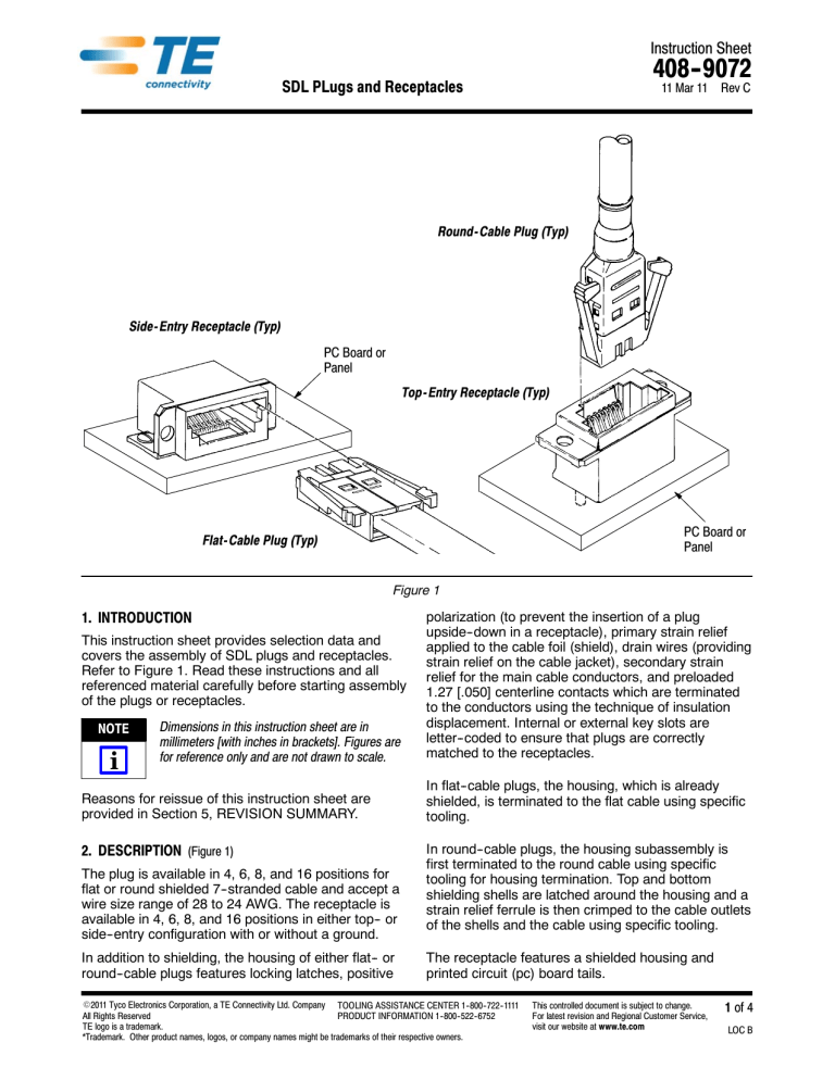
Round- Cable Plug (Typ)
Side- Entry Receptacle (Typ)
PC Board or
Panel
Top- Entry Receptacle (Typ)
PC Board or
Panel
Flat- Cable Plug (Typ)
Figure 1
1. INTRODUCTION
This instruction sheet provides selection data and
covers the assembly of SDL plugs and receptacles.
Refer to Figure 1. Read these instructions and all
referenced material carefully before starting assembly
of the plugs or receptacles.
NOTE
i
Dimensions in this instruction sheet are in
millimeters [with inches in brackets]. Figures are
for reference only and are not drawn to scale.
Reasons for reissue of this instruction sheet are
provided in Section 5, REVISION SUMMARY.
2. DESCRIPTION (Figure 1)
The plug is available in 4, 6, 8, and 16 positions for
flat or round shielded 7--stranded cable and accept a
wire size range of 28 to 24 AWG. The receptacle is
available in 4, 6, 8, and 16 positions in either top-- or
side--entry configuration with or without a ground.
In addition to shielding, the housing of either flat-- or
round--cable plugs features locking latches, positive
polarization (to prevent the insertion of a plug
upside--down in a receptacle), primary strain relief
applied to the cable foil (shield), drain wires (providing
strain relief on the cable jacket), secondary strain
relief for the main cable conductors, and preloaded
1.27 [.050] centerline contacts which are terminated
to the conductors using the technique of insulation
displacement. Internal or external key slots are
letter--coded to ensure that plugs are correctly
matched to the receptacles.
In flat--cable plugs, the housing, which is already
shielded, is terminated to the flat cable using specific
tooling.
In round--cable plugs, the housing subassembly is
first terminated to the round cable using specific
tooling for housing termination. Top and bottom
shielding shells are latched around the housing and a
strain relief ferrule is then crimped to the cable outlets
of the shells and the cable using specific tooling.
The receptacle features a shielded housing and
printed circuit (pc) board tails.
E2011 Tyco Electronics Corporation, a TE Connectivity Ltd. Company TOOLING ASSISTANCE CENTER 1--800--722--1111
All Rights Reserved
PRODUCT INFORMATION 1--800--522--6752
TE logo is a trademark.
*Trademark. Other product names, logos, or company names might be trademarks of their respective owners.
This controlled document is subject to change.
For latest revision and Regional Customer Service,
visit our website at www.te.com
1 of 4
LOC B
408- 9072
3. ASSEMBLY PROCEDURE
3.2. Plug for Round Cable
1. Select the appropriate plug housing, top and
bottom shielding shells, ferrule, and tooling from
Figure 3. If applicable, slide the optional plug boot
(small end first) a few inches back from the end of
the cable.
3.1. Plug for Flat Cable
1. Select appropriate plug and tooling. Refer to
Figure 2.
NOTE
i
Refer to Instruction Sheet 408--9114 for tool
crimp height adjustment procedure for flat--cable
plugs.
NOTE
i
2. Strip 10.41+0.25 [.410+.010] of the outer jacket
from the cable exposing the insulated conductors.
Refer to Instruction Sheet 408--9115 for tool
crimp height adjustment procedure for
round--cable plugs.
2. Refer to Figure 3 for ferrule orientation, and
slide it a few inches back from the end of the
cable.
3. Fold the cable foil and drain wires back as
shown in Figure 2.
3. Strip the required length of the outer jacket from
the cable exposing the colored insulated
conductors. Refer to Application Specification
114--2090 for stripping dimensions.
4. Refer to the instructional material packaged with
the die assembly and hand tool or power unit and
die holder assembly, and terminate the cable
conductors of the plug.
4. Fold the cable foil and drain wires back as
shown in Figure 3.
5. Refer to Paragraph 3.3., and inspect the
terminated plug for proper crimp height.
For specific inspection requirements, refer to
Application Specification 114--2086.
5. Refer to Instruction Sheet 408--9114, and
terminate the conductors and plug housing.
Flat- Cable SDL Plug
Drain Wire
Foil
PLUG
FLAT CABLE
TOOLING
WIRE SIZE
(AWG)
PART NUMBERS
POSITION
CONDUCTORS
DIE ASSEMBLY
X--1761184--1
4
4
X--1761184--2
6
6
X--1761184--3
8
8
X--1761184--6
16
16
58261--6
Y--1761187--1
4
4
58261--1
Y--1761187--3
8
8
Y--1761187--6
16
16
POWER UNIT OR HAND TOOL
58261--1
24
26 or 28
58261--2
58261--3
Pneumatic Power Unit 312522--1
312522 1
(With Die Holder 58201--1)
or
Hand Tool 58194--1
58261--3
58261--6
S The X denotes keying number 1, 3, 4, or 5. The Y denotes keying number 1 or 5.
Call PRODUCT INFORMATION at the number at the bottom of page 1 for available keying.
Figure 2
2 of 4
Rev C
408- 9072
Round- Cable Plug
Top Shield
Shield Barrel
Drain Wire
Bottom Shield
Ferrule
Shield Barrel
PLUG
WIRE SIZE
PLUG
WIRE SIZE
PART NUMBERS
(AWG)
PART NUMBERS
(AWG)
POSITION
X--520424--1
X--520424--2
X--520424--3
X--520532--1
24
X--520424--6
X--520532--2
X--520532--3
28 26
28--26
X--520532--6
FERRULE
PLUG
TOP
SHIELD
TOOLING
BOTTOM
SHIELD
DIE
ASSEMBLY
POWER UNIT
OR HAND TOOL
Pneumatic Power
Unit 312522--1
312522 1
(With Die Holder
58201 1)
58201--1)
or
H d Tool
Hand
T l
58194--1
4
520460--1 520461--1
58195--1
6
520462--1 520463--1
58195--2
8
520464--1 520465--1
58195--3
16
520466--1 520467--1
58195--6
CABLE
TOOLING
PART NUMBER
POSITION
OPTIONAL
PLUG BOOT
OUTSIDE INSULATION DIAMETER RANGE
DIE
ASSEMBLY
520432--1
4
520851--1
3.73--4.42 [.147--.174]
0--58166--1
520433--1
4
520851--1
4.72--5.08 [.186--.200]
0--58166--2
—
6
—
4.27--5.08 [.168--.200]
—
520435--1
6
520852--1
5.36--5.72 [.211--.225]
1--58166--1
520436--1
8
520853--1
4.55--5.38 [.179--.212]
0--58166--5
520437--1
8
520853--1
5.69--6.20 [.224--.244]
1--58166--2
520440--1
16
520854--1
5.82--6.91 [.229--.272]
0--58166--7
520441--1
16
520854--1
7.32--7.82 [.288--.308]
1--58166--3
POWER UNIT
OR HAND TOOL
Pneumatic
P
ti Power
P
Unit 69365-2
69365--2
(With Die Holder
58201 1)
58201--1)
or
Hand Tool
69710 1
69710--1
S The X denotes keying number 1, 3, or 5. Call PRODUCT INFORMATION at the number at the bottom of page 1 for available keying.
Figure 3
6. Refer to Paragraph 3.3., and inspect the
terminated plug for proper crimp height.
For specific inspection requirements, refer to
Application Specification 114--2090.
7. Snap the top and bottom shielding shells
together around the plug housing subassembly to
establish shielding.
Rev C
8. Fold the foil and drain wire over the cable outlet
of the shield assembly, and slide the ferrule as far
forward as possible over the cable outlet of the
shield assembly.
9. Refer to 408--9039, and crimp the ferrule to the
cable and plug.
10. If applicable, slide the optional plug boot over
the assembly.
3 of 4
408- 9072
3.3. Crimp Height Inspection
4. MATING PLUG AND RECEPTACLE
Proper crimp height of the terminated plug is given in
Figure 4.
6.86+0.08
[.270+.003]
Crimp Height
Flat-- Cable Plug
Shown
Contact
The keying letter codes of mating plugs and
receptacles must be identical. Plugs and receptacles
with dissimilar keying letter codes will not mate
without the use of excessive force. When mating a
plug to a receptacle, ensure that the two plastic plug
latches are engaged by pulling lightly on the plug after
mating.
To remove a plug from a receptacle, grasp the plug by
squeezing the plastic plug latches against the body of
the plug and pull it straight out.
Conductor
Figure 4
3.4. Mounting the Receptacle
5. REVISION SUMMARY
Mount the receptacle according to 114--2081.
Revisions to this instruction sheet include:
S Updated instruction sheet to corporate
requirements
Side- Entry Receptacle (Typ)
Top- Entry Receptacle (Typ)
Keys
Offset
Flange
Polarization
Contacts
Grounding Leg(s)
(Optional)
RECEPTACLE PART NUMBERH
SIDE-- ENTRY
POSITION
WITHOUT GROUND
WITH GROUND
WITH OFFSET FLANGE
TOP-- ENTRY
(Without Ground)
4
X--1761182--1
X--1761185--1
X--1761186--1
X--1761183--1
6
—
X--1761185--2
—
X--1761183--2
8
—
X--1761185--3
X--1761186--3
X--1761183--3
16
X--1761182--6
X--1761185--6
X--1761186--6
X--1761183--6
H Prefix number of part numbers denotes keying configuration. For example, 1-- 1761182-- 1 has keying letter code A.
Call PRODUCT INFORMATION at the number at the bottom of page 1 for available keying.
Figure 5
4 of 4
Rev C


