LHT EZ9 4844K Light Kit
Instructions for EZGO TXT Models
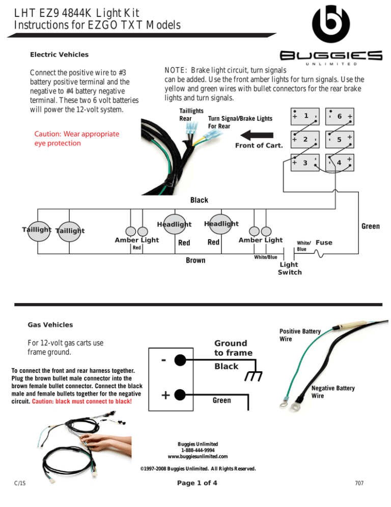
Electric Vehicles
-
5
+
4
+
+
-
6
-
-
3
-
2
-
Front of Cart.
+
Caution: Wear appropriate
eye protection
1
+
Taillights
Rear
Turn Signal/Brake Lights
For Rear
+
NOTE: Brake light circuit, turn signals
can be added. Use the front amber lights for turn signals. Use the
yellow and green wires with bullet connectors for the rear brake
lights and turn signals.
Connect the positive wire to #3
battery positive terminal and the
negative to #4 battery negative
terminal. These two 6 volt batteries
will power the 12-volt system.
Black
Headlight
Taillight Taillight
Amber Light
Headlight
Red
Red
Red
Green
Amber Light
White/
Blue
Fuse
White/Blue
Brown
Light
Switch
Gas Vehicles
For 12-volt gas carts use
frame ground.
Ground
to frame
-
To connect the front and rear harness together.
Plug the brown bullet male connector into the
brown female bullet connector. Connect the black
male and female bullets together for the negative
circuit. Caution: black must connect to black!
Positive Battery
Wire
Black
+
Green
Negative Battery
Wire
Buggies Unlimited
1-888-444-9994
www.buggiesunlimited.com
©1997-2008 Buggies Unlimited. All Rights Reserved.
C/1S
Page 1 of 4
707
LHT EZ9 4844K Light Kit
Instructions for EZGO TXT Models
Remove seat. If so equipped, turn RUN/TOW switch off. Disconnect
batteries at system negative and system positive. The forward battery on
the passenger side of vehicle is the positive terminal and the rear battery
on passenger side is the negative terminal. Observe cart wire loom (black
corrugated) under passenger side seat in front of controller cover. Insert
harness into frame hole alongside cart harness. (see picture A) Feed wire
loom to front of cart following cart harness. After passing through the
steering holes, route harness behind steering tube and secure to the frame
with strap-tie (see picture B).
HEADLIGHT INSTALLATION:
Install light bar to brackets using 10mm head M6 x 16 hex head screws.
Do not tighten lag screws at this time (see diagram E). Using a 1/4” drill
bit, remove rivets from lower frame shield. Loosen upper retaining screws
1/4” to 3/8” with a 3/8” wrench. It isn’t necessary to remove them completely. The washer can be under the new light bracket. Install 1/4”-20
hex head bolts into lower bracket holes; angle nuts and tighten. Tighten
upper bracket screws. For added harness retention, remove cup holders
and tie harness to main cart harness. Connect harness to light bar.
TAILLIGHT HARNESS:
Route rear light harness alongside motor cables between the controller
box and batteries. Route the longer harness section, behind battery bank,
outside of rear shock absorber and to the rear of cart. Route shorter
harness outside of right rear shock absorber to right rear of cart. Using
template, cut holes in rear body for taillights and install light in hole. Drill
1/8” pilot holes for bezel mounting in body and insert #8 screws in bezel.
(see picture C).
A
B
B
3
LIGHT SWITCH MOUNTING:
The light switch included with this kit is intended for mounting in the
dash. The installer may decide where the switch will be positioned within
the limits of the harness length. Drill ½” hole in body where desired and
install switch and tighten hex nut with 5/8” wrench or socket. Install fuse
(20-25amp).
Connect positive wire (green) to battery 3 (pos +) terminal.
4
C
Connect negative wire (black) to # 4 (neg -) terminal.
NOTE: For gas carts use a frame ground.
Page 2 of 4
C
LHT EZ9 4844K Light Kit
Instructions for EZGO TXT Models
D. Bracket Mounting
Diagram E
Plug In For
Rear Lights
Battery
Negative
Rear Turn/Brake
Connections Are
The Yellow and Green
Bullet Connectors
Battery Positive
Light
Switch
Amber Light plugs are used
for front turn signals (optional),
disconnect the plugs for turn
signal applications and connect
turn signal leads to the amber
light plug.
Plug In For
Front Lights
Light Bar
Page 3 of 4
Page 3 of 4
LHT EZ9 4844K Light Kit
Instructions for EZGO TXT Models
Taillight Template
311/16
Buggies Unlimited
1-888-444-9994
www.buggiesunlimited.com
©1997-2008 Buggies Unlimited. All Rights Reserved.
Page 4 of 4
Cut along dotted line.
67/16
*NOTE - In order for
the template to
line up, you must
print this sheet
at 100%. You
cannot scale
the printout
in anyway.
Shaded area is what you
should have as your template.
This is the passenger’s
side template. Flip
over for driver’s side.
Right
Place template 2” over
from the side and 1-1/2”
up from bumper.

