PRODUCT BULLETIN SSB 001-5401-1100
PROPULSION ORDER TELEGRAPH
DIGITAL SYSTEM
Series
5401-1100
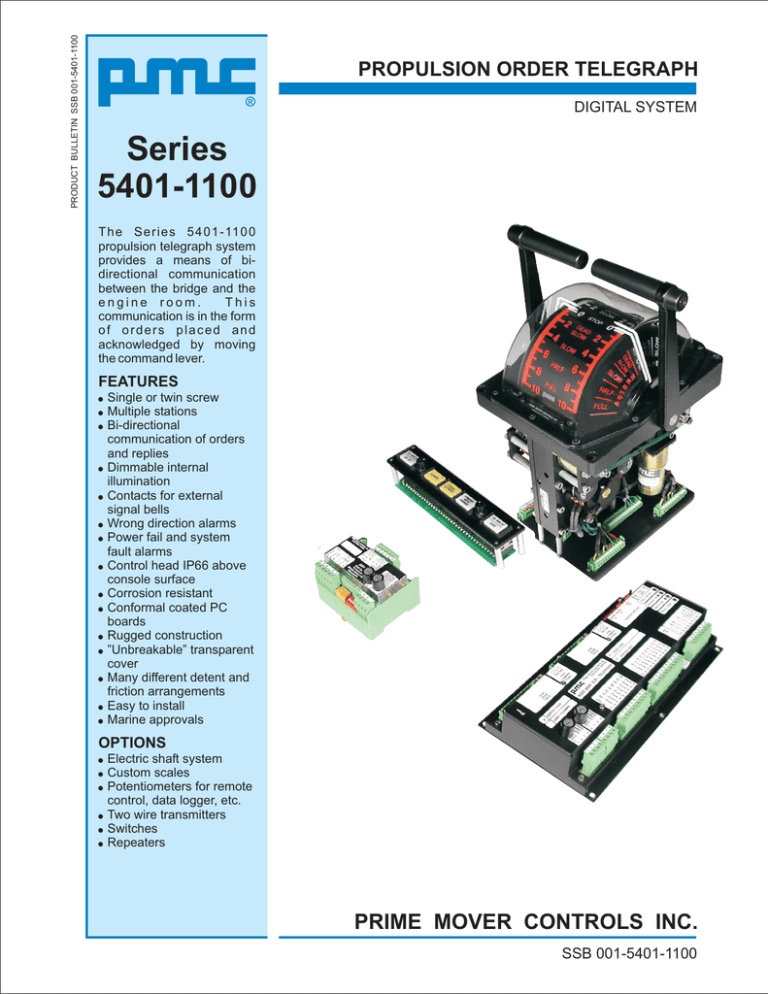
The Series 5401-1100
propulsion telegraph system
provides a means of bidirectional communication
between the bridge and the
engine room.
This
communication is in the form
of orders placed and
acknowledged by moving
the command lever.
FEATURES
! Single or twin screw
! Multiple stations
! Bi-directional
communication of orders
and replies
! Dimmable internal
illumination
! Contacts for external
signal bells
! Wrong direction alarms
! Power fail and system
fault alarms
! Control head IP66 above
console surface
! Corrosion resistant
! Conformal coated PC
boards
! Rugged construction
! ”Unbreakable” transparent
cover
! Many different detent and
friction arrangements
! Easy to install
! Marine approvals
OPTIONS
! Electric shaft system
! Custom scales
! Potentiometers for remote
control, data logger, etc.
! Two wire transmitters
! Switches
! Repeaters
PRIME MOVER CONTROLS INC.
SSB 001-5401-1100
PROPULSION ORDER TELEGRAPH
Propulsion Order Telegraph System
Series 8503-2000 Digital Servo Controllers are
used in conjunction with Type 5401-1100 control
heads to form a traditional lever style telegraph
system.
Auxiliary Orders
Auxiliary telegraph orders such as Standby, Cancel
Standby and Finished With Engines can be
integrated into the lever telegraph. Auxiliary
telegraph orders can also be external pushbuttons.
The propulsion telegraph system provides a means
of bi-directional communication between the
bridge and the engine room. This communication is
in the form of orders placed and acknowledged by
moving the command levers.
Wrong Direction
An optional wrong direction alarm, with adjustable
time delay, is activated when the direction of
propulsion is not the same as the acknowledged
telegraph order. This feature advises the engineer
and captain when the machinery direction does not
match the acknowledged order or if the machinery
drifts to a direction other than the established
setting. Ahead, Stop and Astern are considered
distinct directions and are monitored by the wrong
direction circuitry.
The system uses dual 24VDC inputs from ship’s
power supplies and serial communication with error
detection to ensure trouble free operation.
Relay outputs are provided for an order bell and a
wrong direction alarm.
Telegraph Orders
An order is placed by moving the lever at the bridge
station in command to the desired order. This causes
the reply pointers at all engine room stations to
move to the same position as the command lever on
the bridge.
Whenever the reply pointer and the lever at an in
command telegraph are not aligned, the external
bells sound, at both in command locations, to
indicate a new order.
Once the in command engine room lever is moved
to align with it’s own reply pointer, all bridge reply
pointers will follow up and align with the engine
room lever. All audible devices will silence. The
engine room can transmit orders to the bridge in the
same manner.
Multiple Station System
The propulsion telegraph system can operate from
multiple bridge and engine room stations.
When a ship has one bridge station and one engine
room station, both the bridge and engine room
station are always in command.
When a ship has more than one station in the bridge
and/or more than one station in the engine room
command transfer is required. Generally a
telegraph command transfer button is used to
transfer command.
The control transfer logic can be performed by the
Digital Servo Controller or via external logic (PLC,
relays, or control transfer boards).
When auxiliary telegraph orders are present on the
lever telegraph scale, wrong direction alarms are
disabled for any acknowledged auxiliary order.
When external push buttons are used for the
auxiliary telegraph orders, wrong direction alarms
are disabled for acknowledged Finished With
Engines and Bridge Control orders, but enabled for
Standby and Cancel Standby orders.
Pushbutton Telegraph Stations
Series 8202-1000 Push Button Telegraphs can be
connected to a Type 8503-2000 Digital Servo
Controller. The lever telegraph and the push button
telegraph communicate on the same network.
Command Position
Optional command signal transmitters can be
installed at the factory. These transmitters work
independently of the telegraph circuitry in the
Digital Servo Controller. Each transmitter has it's
own power supply with a self resetting internal fuse.
Even with a complete failure of other circuitry on
the Digital Servo Controller the transmitter will
continue to function properly.
Diagnostics
Troubleshooting guidance is provided by a
Watchdog LED and a Fault Code LED. Under
normal operating conditions the Watchdog LED
will flash.
The Fault Code LED flashes two digit codes which
correspond to particular fault conditions. A fault
relay opens on a general system fault.
PRIME MOVER CONTROLS
PROPULSION ORDER TELEGRAPH
C
KB
1
31 32 33 34 35 36 37 38
2
-
3
4
7
6
6
7
8
8
9
9
1
3
4
5
6
7
DIPS
1-8
8
C
SW
T1
CONFIGURATION SWITCHES
DE
TEST
MODE
WATCHDOG
RX
TX
KB
UNIT
ID
KF
FAULT CODE
S/N
DATA
11 12 13 14 15 16 17 18 19
11 12 13 14 15 16 17 18 19
20 21 22 23 24 25 26 27 28 29 30
20 21 22 23 24 25 26 27 28 29 30
SW
T2
TEST / SETUP
SERVICE PIN
P/N
31 32 33 34 35 36 37 38
C
DE
H
I J
I J
WHEELHOUSE #1
2
KB
KB
DE
KA
FUSE
24VDC
4
VOUT
PORT
COMMAND
SIGNAL
3
2
C
ROTARY ROTARY
A
B
STBD
COMMAND
SIGNAL
TX \ RX ACTIVE
DE
KB
1
+
-
+
RX
TX
KF
TX \ RX ACTIVE
KB
KA
DE
8503-2000 E/S - TELEGRAPH
LEVER TELEGRAPH
FUSE
24VDC
31 32 33 34 35 36 37 38
20 21 22 23 24 25 26 27 28 29 30
11 12 13 14 15 16 17 18 19
PRIME MOVER CONTROLS INC.
VANCOUVER, CANADA
ELECTRIC SHAFT
FAULT CODE
UNIT
ID
20 21 22 23 24 25 26 27 28 29 30
STBD
LEVER
CABLE
I0
I1
I2
I3
I4
I5
I6
I7
I8
I9
WATCHDOG
ZERO SPAN
PORT
COMMAND
SIGNAL
O0
O1
O2
O3
O4
O5
O6
O7
SERVICE PIN
DATA
9
ZERO SPAN
PORT
LEVER
CABLE
STBD
COMMAND
SIGNAL
CONFIGURATION SWITCHES
I0
I1
I2
I3
I4
I5
I6
I7
I8
I9
O0
O1
O2
O3
O4
O5
O6
O7
SW
T2
KB
KB
KB
KB
I J
VOUT
H
I J
PORT
COMMAND
SIGNAL
H
I J
STBD
COMMAND
SIGNAL
H
+
C
I J
+
DE
TEST
MODE
31 32 33 34 35 36 37 38
H
C
SW
T1
TEST / SETUP
H
8
S/N
11 12 13 14 15 16 17 18 19
9
8
7
F G
7
6
6
SILENCE
F G
4
5
STBD WRONG DIR
F G
3
8
4
DIPS
1-8
FINISHED
WITH
ENGINES
F G
-
7
6
3
CANCEL
STANDBY
F G
2
FUSE
24VDC
4
2
F G
1
3
2
1
DE
F G
-
1
C
P/N
8503-2000 E/S - TELEGRAPH
LEVER TELEGRAPH
FUSE
STBD
COMMAND
SIGNAL
STANDBY
I J
DE
F G
PRIME MOVER CONTROLS INC.
VANCOUVER, CANADA
ELECTRIC SHAFT
24VDC
STBD
LEVER
CABLE
LAMP TEST
ROTARY ROTARY
A
B
ZERO SPAN
PORT
COMMAND
SIGNAL
PORT WRONG DIR
SILENCE
H
C
ZERO SPAN
PORT
LEVER
CABLE
STBD WRONG DIR
I J
FINISHED
WITH
ENGINES
CANCEL
STANDBY
STANDBY
LAMP TEST
H
PORT WRONG DIR
WHEELHOUSE #2
TYPICAL
THREE STATION
PROPULSION ORDER
TELEGRAPH SYSTEM
FINISHED
WITH
ENGINES
STBD WRONG DIR
SILENCE
I J
4
6
7
9
7
8
C
DE
KB
KB
6
SW
T1
TEST
MODE
WATCHDOG
20 21 22 23 24 25 26 27 28 29 30
20 21 22 23 24 25 26 27 28 29 30
11 12 13 14 15 16 17 18 19
RX
TX \ RX ACTIVE
TX
KA
KB
I0
I1
I2
I3
I4
I5
I6
I7
I8
I9
KF
FAULT CODE
UNIT
ID
DATA
11 12 13 14 15 16 17 18 19
SW
T2
TEST / SETUP
SERVICE PIN
S/N
O0
O1
O2
O3
O4
O5
O6
O7
VOUT
STBD
COMMAND
SIGNAL
8
9
5
CONFIGURATION SWITCHES
31 32 33 34 35 36 37 38
C
DE
KB
+
+
PORT
COMMAND
SIGNAL
3
8
4
TO ALARM SYSTEM
31 32 33 34 35 36 37 38
H
-
7
6
H
2
FUSE
24VDC
4
3
DIPS
1-8
F G
1
3
2
I J
-
1
2
P/N
8503-2000 E/S - TELEGRAPH
LEVER TELEGRAPH
FUSE
24VDC
STBD
COMMAND
SIGNAL
F G
PRIME MOVER CONTROLS INC.
VANCOUVER, CANADA
ELECTRIC SHAFT
1
DE
F G
DIGITAL SERVO
CONTROLLER
STBD
LEVER
CABLE
C
F G
KB
DE
ROTARY ROTARY
A
B
ZERO SPAN
PORT
COMMAND
SIGNAL
H
C
ZERO SPAN
PORT
LEVER
CABLE
I J
CANCEL
STANDBY
STANDBY
LAMP TEST
H
PORT WRONG DIR
I J
PRIMARY 24VDC SUPPLY
SECONDARY 24VDC SUPPLY
8545-1100-
COMMUNICATION
TERMINATOR
1
1
1
1
2
2
2
FULL
AHD
PRIME MOVER CONTROLS INC.
VANCOUVER CANADA
HALF
AHD
SLOW
AHD
STOP
1
4
PORT
BRIDGE
CONTROL
STANDBY
STBD
BRIDGE
CONTROL
HALF
AHD
FINISHED
WITH
ENGINES
SLOW
AHD
PORT
WRONG
DIRECTION
STBD
WRONG
DIRECTION
TEST
FAULT
SILENCE
HALF
AST
FULL
AST
PORT
FULL
AHD
CANCEL
STANDBY
STOP
OPTIONAL LOCAL AT ENGINE TELEGRAPH
SERIES 8202-1000 PUSHBUTTON STYLE SHOWN
SLOW
AST
HALF
AST
PRIME MOVER CONTROLS INC.
VANCOUVER, CANADA
8202-1200 PROPULSION TELEGRAPH
FULL
AST
STBD
4
3
2
1
5
7
8
9
DATA
10
6
8202-1900
Telegraph
Wrong Direction
Collector
KF
DATA
9 10
NET
8
PRIME MOVER CONTROLS INC.
VANCOUVER, CANADA
7
ERROR
CODE
6
SERVICE PIN
AST
5
A
S
T
AST
AHD
STBD
A
H
D
AHD
PORT
WRONG DIRECTION
COLLECTOR
(OPTIONAL)
11 12 13 14 15 16
16 15 14 13 12 11
5
6
4
FUSE
3
3
FUSE
2
PRI.
SEC.
24VDC 24VDC
1
WATCHDOG
A
A
H
S
D
T
2
SLOW
AST
RESET
STBD
PORT
TERMINATOR
2
AHD
AST
PORT WRONG DIR SWITCHES
OPEN IN SELECTED DIRECTION
AHD
AST
STBD WRONG DIR SWITCHES
OPEN IN SELECTED DIRECTION
ENGINE CONTROL ROOM
PRIME MOVER CONTROLS
RELATED PRODUCT BULLETINS
PROPULSION TELEGRAPH/CONTROL HEAD
TYPE PCH
Series
5400-1100
5401-1100
Series 8202-1000
Propulsion Telegraph
PRODUCT BULLETIN SB 8202-1000
PRODUCT BULLETIN SB 5400-1100
Series 5400-1100/5401-1100
Propulsion Telegraph/Control Head
PROPULSION TELEGRAPH
Series
8202-1000
The PMC series 8202-1000
Propulsion Order Telegraph
is a compact, modular,
microcontroller marine
telegraph for single or twin
screw systems. It operates
as a stand alone or backup
system. The 8202 functions
independently of the ship's
main propulsion controls and
allows emergency operation
when primary remote
controls fail.
The Series 5400-1100
Propulsion Control Head is a
versatile remote control
device.
The Series 5401-1100
Propulsion Telegraph is a
traditional lever telegraph.
FEATURES
! Single or twin screw
! Dimmable internal
illumination
! IP66 above console
! Corrosion resistant
! Rugged construction
! ”Unbreakable” transparent
cover
! Many different detent and
friction arrangements
! Easy to install
! Removable terminal
blocks
! Marine approvals
FEATURES
! Eleven Port orders, eleven
Starboard orders, Bridge
Control orders, and a
Finished with Engines
order
! I n d e p e n d e n t Sta n d b y
orders
! Optional wrong direction
alarms
! Single or twin screw
! Forward or Aft facing
! Up to six engine room units
and nine bridge units
! Super bright order
indicators for daylight
operation
! Backlit buttons for night
operations
! Bridge units are dimmable
! Reliable communication
and transceiver technology
for the marine environment
! Communication cable
length up to 2700 meters
! Dual 24VDC inputs use
ship's power supplies
! Relay outputs for external
order and wrong direction
bells
! Relay output for unit fault
(communication, CPU,
power or setup fault)
! Self diagnostics with status
indication
! 144mm DIN mounting
! IP65 splash proof front
OPTIONS
! Electric shaft system
! Telegraph system
! Auto transfer system
! Multiple potentiometers for
remote control,
datalogger, etc.
! Multiple two wire
transmitters
# 4-20mA
# 20-4mA
# 20-4-20mA
# custom
! Multiple switches
! Pneumatic control
! Custom scales
! Dual lever coupling
mechanism
PRIME MOVER CONTROLS INC.
BRIDGE
CONTROL
STANDBY
A
H
D
HALF
AHD
FINISHED
WITH
ENGINES
SLOW
AHD
STOP
WRONG DIRECTION
TEST
A
S
T
FULL
AHD
CANCEL
STANDBY
SLOW
AST
FAULT
SILENCE
HALF
AST
DIM
DIM
PRIME MOVER CONTROLS INC.
VANCOUVER, CANADA
8202-1000 PROPULSION TELEGRAPH
FULL
AST
single screw
STBD
PORT
FULL
AHD
HALF
AHD
SLOW
AHD
STOP
SLOW
AST
HALF
AST
FULL
AST
PORT
BRIDGE
CONTROL
STBD
BRIDGE
CONTROL
STANDBY
FULL
AHD
CANCEL
STANDBY
HALF
AHD
FINISHED
WITH
ENGINES
SLOW
AHD
PORT
WRONG
DIRECTION
STBD
WRONG
DIRECTION
STOP
TEST
SLOW
AST
FAULT
SILENCE
HALF
AST
DIM
DIM
PRIME MOVER CONTROLS INC.
VANCOUVER, CANADA
8202-1200 PROPULSION TELEGRAPH
FULL
AST
STBD
PORT
twin screw
PRIME MOVER CONTROLS INC.
SB 5400-1100
SB 8202-1000
Series 8503-2000
Digital Servo Controller
Type 8202-1900
Telegraph Wrong Direction Collector
DIGITAL SERVO CONTROLLER
ELECTRIC SHAFT/PROPULSION TELEGRAPH
Series
8503-2000
Electric Shaft
The electric shaft control
system is an electrical
alternative to mechanical
shafting for interconnecting
remote control levers on a
ship. Moving the control
lever at one station causes
all other levers in the system
to follow.
This provides
continuous display at all
stations of the position of the
lever at the controlling
station. Because all control
levers are continually
aligned, control transfer
between stations is smooth
and "bumpless".
PROPULSION TELEGRAPH
TELEGRAPH WRONG DIRECTION COLLECTOR
Type
8202-1900
The PMC Type 8202-1900
Telegraph Wrong Direction
Collector provides direction
monitoring in the Ahead,
Astern and Stop positions.
Wrong direction status is
visually and audibly alarmed
at the telegraph stations.
FEATURES
! Single or twin screw
! Reliable communication
and transceiver technology
for the marine environment
! Communication cable
length up to 2700 meters
! Dual 24VDC inputs use
ship's power supplies
! Relay output for unit fault
(communication, CPU,
power or setup fault)
! Self diagnostics with status
indication
! TS 35×3,5 rail mount
! IP40
Telegraph
The propulsion telegraph
provides a means of l
communication between the
bridge and engine room.
This communication is in the
form of orders placed and
acknowledged by moving
the command / reply lever to
align with the acknowledge /
command pointer.
FEATURES
! Single or twin screw
! Up to nine bridge units and
six engine room units
! Telegraph compatible with
Type 8202 push button
telegraphs
! Optional independent
command position outputs
(4-20mA or 2k-12kHz)
! Optional gateway for
connecting to data logger,
printer or PLC
! Reliable communication
and transceiver technology
for the marine environment
! Dual 24VDC inputs use
ship's power supplies
! Self diagnostics with status
indication
! Relay output for unit fault
! Marine approvals
PRODUCT BULLETIN SB 8202-1900
SB 8202-1000
PRODUCT BULLETIN SB 8503-2000
SB 5400-1100
SB 8503-2000
PRIME MOVER CONTROLS INC.
PRIME MOVER CONTROLS INC.
SB 8503-2000
SB 8503-2000
SB 8202-1900
SB 8202-1900
PRIME MOVER CONTROLS INC.
PROD_REF\5401_TLG\C_BULLTN\SSB-001-5401-1100R00.CDR
3600 GILMORE WAY, BURNABY B.C. CANADA V5G 4R8
TEL (604) 433-4644 FAX (604) 433-5570 www.pmc-controls.com
ALL RIGHTS RESERVED


